
Motor Connection for Clockwise and Counterclockwise Direction of Rotation (photo credit: johndearmond.com)
Star-delta (Y-Δ, wye-delta) starting
Star-delta (in North America the designation “wye-delta” is commonly used instead) starting is the simplest method for reducing the starting current of a motor. The technique can be used with all squirrel-cage induction motors that are delta-connected for normal operation and whose windings ends are individually connected to terminals.
The reduction of the motor current causes a reduction of the starting torque.
Transient currents //
When the delta contactor connects at adverse vectorial positions of the supply voltage and the rotor field, transient processes could occur in the motor that could lead to larger current peaks than at switching-on the delta-connected motor .
This can result in the making capacity of the contactors being exceeded with as a consequence welding of contacts.
The transient currents can be reduced by appropriate wiring of the main circuit (Figure 1). Besides the load on the contactors, this also reduces the dynamic stress on the windings-heads in the motor.
Lower transient currents peaks with correct wiring
Clockwise rotation
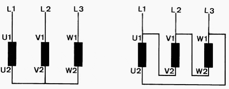
Figure 1 – Correct connection of motor phases for clockwise rotation
During the de-energized switching interval, the rotor falls back against the rotating field of the power supply. Its magnetic field induces a decaying residual voltage in the stator – in the voltage phasor diagram Figure 2 for the pole conductor L1 entered as UL1’-N.
When connecting to delta (Fig. 1 and Fig. 2) the mains voltage UL1-L3 is applied to the stator winding, across which this residual voltage is still present. The differential voltage ∆U is relatively small, thanks to the favorable vectorial position of the residual voltage UL1’-N and the supply voltage UL1-L3 that are approximately oriented in the same direction.
Thus the current surge generated by this resultant voltage will also remain small.
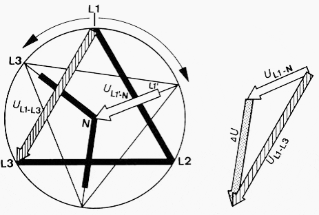
Figure 2 – Phasor diagram for star-delta with correctly connected motor phases for clockwise rotation
High transient current surge with incorrect wiring
The motor also turns clockwise when the terminals are connected according to Figure 3.
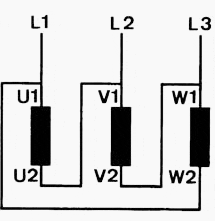
Figure 3 – Incorrect connection of the motor phases also produces clockwise turning
A decaying residual voltage acts again with lagging phase position in the stator during the switching interval. On switching to delta, the phase winding with the phasor UL1’-N is connected to the supply phase UL1-L2. These two voltages however have totally different vectorial directions, the differential voltage ∆U is high and results in a correspondingly high transient current surge.
Switching from star to delta produces the phasor diagram Figure 4.
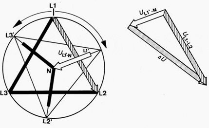
Figure 4 – Phasor diagram for connections of the motor phases according to Figure 3. This produces a high transient current surge because of the adverse vector position.
Counterclockwise sense of rotation
To run the motor in the counterclockwise direction, it is not enough to swap around two phases at any point. This would produce the same relationships as described above. In order to keep the transient current surge from star to delta connection as small as possible the wiring must be arranged as in Figure 5.
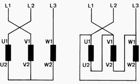
Figure 5 – Correct connection of the motor phases for counterclockwise rotation of motor
Reference // Low-Voltage Switchgear and Controlgear – Allen-Bradley (Download here)


