Quantcast
Channel: Electric Motor - Technical Articles | EEP - Electrical Engineering Portal
Viewing all 139 articles
Browse latest View live

Few Words About Synchronous Machines

$
0
0
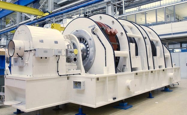
Gearless synchronous generator for wind power plants developed by SIEMENS

Figure 1 - Gearless synchronous generator for wind power plants developed by SIEMENS

Introduction to Synchronous Machine

There are two main types of synchronous machine: cylindrical rotor and salient pole.

In general, the former is confined to 2 and 4 pole turbine generators, while salient pole types are built with 4 poles upwards and include most classes of duty. Both classes of machine are similar in so far that each has a stator carrying a three-phase winding distributed over its inner periphery.

Within the stator bore is carried the rotor which is magnetised by a winding carrying d.c. current.

The essential difference between the two classes of machine lies in the rotor construction.

The cylindrical rotor type has a uniformly cylindrical rotor that carries its excitation winding distributed over a number of slots around its periphery. This construction is unsuited to multi-polar machines but it is very sound mechanically.

Hence it is particularly well adapted for the highest speed electrical machines and is universally employed for two pole units, plus some four pole units.

The salient pole type has poles that are physically separate, each carrying a concentrated excitation winding. This type of construction is in many ways complementary to that of the cylindrical rotor and is employed in machines having 4 poles or more. Except in special cases its use is exclusive in machines having more than 6 poles.

Figure 1 above illustrates a gearless synchronous generator for wind power plants developed by SIEMENS installed in a power plant. The unit, which has an extremely high efficiency rating of 98%, uses permanent magnets to convert wind energy from the rotor into electricity. The gearless generator avoids losses due to friction and heat and starts to operate even at low winds or in brief gusts. Because of this innovative design the generator doesn’t need gear oil and has fewer mechanical parts subject to wear and tear, which means less downtime.

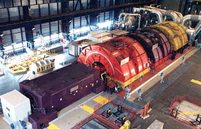
Two and four pole generators are most often used in applications where steam or gas turbines are used as the driver. This is because the steam turbine tends to be suited to high rotational speeds.

Four pole steam turbine generators are most often found in nuclear power stations as the relative wetness of the steam makes the high rotational speed of a two-pole design unsuitable.

SIEMENS's 2 pole generators customized for the use on gas and steam turbines

SIEMENS's 2 pole generators customized for the use on gas and steam turbines


Large 4-Pole Generators - ALSTOM Power

Large 4-Pole Generators designed by ALSTOM Power for maximum reliability, availability and maintainability. The design also takes into account optimum erection, commissioning, testing and plant layout


Most generators with gas turbine drivers are four pole machines to obtain enhanced mechanical strength in the rotor- since a gearbox is often used to couple the power turbine to the generator, the choice of synchronous speed of the generator is not subject to the same constraints as with steam turbines.

Generators with diesel engine drivers are invariably of four or more pole design, to match the running speed of the driver without using a gearbox. Four-stroke diesel engines usually have a higher running speed than two-stroke engines, so generators having four or six poles are most common.

Two-stroke diesel engines are often derivatives of marine designs with relatively large outputs (circa 30MW is possible) and may have running speeds of the order of 125rpm.

This requires a generator with a large number of poles (48 for a 125rpm, 50Hz generator) and consequently is of large diameter and short axial length. This is a contrast to turbine-driven machines that are of small diameter and long axial length.


Armature Reaction

Armature reaction has the greatest effect on the operation of a synchronous machine with respect both to the load angle at which it operates and to the amount of excitation that it needs.

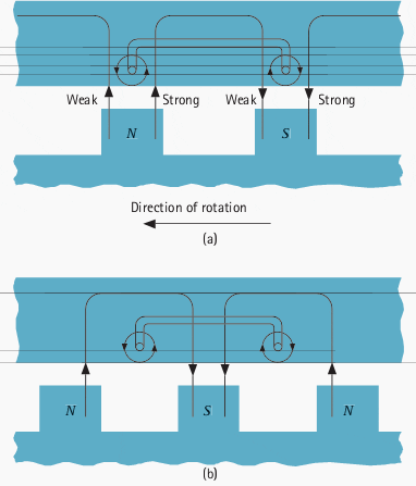
Distortion of flux due to armature reaction

Figure 2 - Distortion of flux due to armature reaction


The phenomenon is most easily explained by considering a simplified ideal generator with full pitch winding operating at unity p.f., zero lag p.f. and zero lead p.f. When operating at unity p.f., the voltage and current in the stator are in phase, the stator current producing a cross magnetising magneto-motive force (m.m.f.) which interacts with that of the rotor, resulting in a distortion of flux across the pole face.

As can be seen from Figure 2 (a) the tendency is to weaken the flux at the leading edge or effectively to distort the field in a manner equivalent to a shift against the direction of rotation.

If the power factor were reduced to zero lagging, the current in the stator would reach its maximum 90° after the voltage and the rotor would therefore be in the position shown in Figure 2 (b). The stator m.m.f. is now acting in direct opposition to the field.

Similarly, for operation at zero leading power factor, the stator m.m.f. would directly assist the rotor m.m.f. This m.m.f. arising from current flowing in the stator is known as ‘armature reaction‘.

Resource: Network Protection and Automation Guide – Areva


Stator Overheating Protection

$
0
0
Stator Overheating Protection

Stator Overheating Protection (on photo bottom of the Motor Stator Winding; by electrical-forensics.com)

Overheating

All motors need protection against overheating resulting from overload, stalled rotor, or unbalanced stator currents.

For complete protection, three-phase motors should have an overload element in each phase. This is because an open circuit in the supply to the power transformer feeding a motor will cause twice as much current to flow in one phase of the motor as in either of the other two phases, as shown in Figure 1.

Consequently, to be sure that there will be an overload element in the most heavily loaded phase no matter which power-transformer phase is open-circuited, one should provide overload elements in all three phases.

In spite of the desirability of overload elements in all three phases, motors rated about 1500 hp and below are generally provided with elements in only two phases, on the assumption that the open-phase condition will be detected and corrected before any motor can overheat.

Illustrating the need for overcurrent protection in each phase

Figure 1 - Illustrating the need for overcurrent protection in each phase


Single-phase motors require an overload element in only one of the two conductors.


Motors Other than Essential Service

Except for some essential-service motors, whose protection will be discussed later, it is the practice for motors rated less than about 1500 hp to provide either replica-type thermal-overload relays or long-time inverse-time-overcurrent relays or direct-acting tripping devices to disconnect a motor from its source of supply in the event of overload.

Which type of relay to use is largely a matter of personal preference.

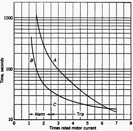
Other things being equal, the replica type will generally provide the best protection because, as shown in Figure 2, its time-current characteristic more nearly matches the heating characteristic of a motor over the full range of overcurrent; also, it may take into account the heating effect of the load on the motor before the overload condition occurred.

Typical motor-heating and protective-relay characteristics

Figure 2 - Typical motor-heating and protective-relay characteristics. A, motor; B, replica relay; C, inverse-time relay.


The inverse-time-overcurrent relay will tend to “overprotect” at low currents and to “under protect” at high currents, as shown in Figure 2.

Inverse-Time Overcurrent type e ICM 21 - ABB

Inverse-Time Overcurrent type e ICM 21 - ABB

However, the overcurrent relay is very easy to adjust and test, and it is self-reset. For continuous-rated motors without service factor or short-time overload ratings, the protective relays or devices should be adjusted to trip at not more than about 115% of rated motor current.

For motors with 115% service factor, tripping should occur at not more than about 125% of rated motor current. For motors with special short-time overload ratings, or with other service factors, the motor characteristic will determine the required tripping characteristic, but the tripping current should not exceed about 140% of rated motor current.

The manufacturer’s recommendations should be obtained in each case.

The overload relays will also provide protection in the event of phase-to-phase short circuits, and in practice one set of such relays serves for both purposes wherever possible.

A survey of the practice of a number of power companies45 showed that a single set of longtime inverse-time-overcurrent relays, adjusted to pick up at 125% to 150% of rated motor current, is used for combined short-circuit and overload protection of non-essential auxiliary motors; they are supplemented by instantaneous overcurrent relays adjusted as already described.

Such inverse-time overload relays must withstand short-circuit currents without damage for as long as it takes to trip the breaker. Also the minimum requirements as to the number of relays or devices for either function must be fulfilled.

Motors rated higher than about 1500 hp are generally provided with resistance temperature detectors embedded in the stator slots between the windings. If such temperature detectors are provided, a single relay operating from these detectors is used instead of the replica-type or inverse-time-overcurrent relays.

Also, current-balance relays capable of operating on about 25% or less unbalance between the phase currents should be supplied. If the motor does not have resistance temperature detectors, but is provided with current-balance relays, a single replica-type thermal overload relay may be substitutedfor the resistance-temperature-detector relay.

Specially cooled or ventilated motors may require other types of protective equipment than those recommended here. For such motors, the manufacturer’s recommendations should be obtained.

Reference 50 gives more useful information on the subject of industrial-motor protection.


Essential-Service Motors

The protection recommended for some essential-service motors is based on minimizing the possibility of unnecessarily tripping the motor, even though such practice may sometimes endanger the motor. In other words, long-time inverse-time overcurrent relays are provided for all motor ratings, but they merely control an alarm and leave tripping in the control of an operator.

Then, for motors that can suffer locked rotor, supplementary instantaneous overcurrent relays, adjusted to pick up at about 200% to 300% of rated motor current are used, and their contacts are connected in series with the contacts of the inverse time-overcurrent relays to trip the motor breaker automatically.

The instantaneous relays should be of the high-reset type to be sure that they will reset when the current returns to normal after the starting inrush has subsided. The protection provided by this type of equipment is illustrated in Figure 3.

Protection characteristic for essential-service motors

Figure 3 - Protection characteristic for essential-service motors. A, motor; B, inverse-time relay; C, instanteneous relay.


For essential-service motors for which automatic tripping is desired in addition to the alarm for overloads between about 115% of rated current and the pickup of the instantaneous overcurrent relays, thermal relays of either the replica type or the resistance temperature-detector type should be used, depending on the size of the motor.

Such relays permit operation for overloads as far as possible beyond the point where the alarm will be sounded, but without damaging the motor to the extent that it must be repaired before it can be used again.

Resource: The ART & SCIENCE of protective relaying – C. Russell Mason

Classes, Speed Control and Starting of DC motors

$
0
0
Classes, Speed Control and Starting of DC motors

Classes, Speed Control and Starting of DC motors (on photo: Sugarcane Mill Rolling DC Motor; 440/220VDC; 500kW; with Shunt-wound construction)

DC Motor Classes

D.C. motors are divided into three classes, as follows:

1. The series-wound motor

In this type (Figure 1) the field is in series with the armature. This type of DC motor is only used for direct coupling and other work where the load (or part of the load) is permanently coupled to the motor. This will be seen from the speed-torque characteristic, which shows that on no load or light load the speed will be very high and therefore dangerous.

Series-wound motor

Figure 1 - Series-wound motor

2. The shunt-wound motor

In this case the field is in parallel with the armature, as shown in Figure 2, and the shunt motor is the standard type of d.c. motor for ordinary purposes.

Its speed is nearly constant, falling off as the load increases due to resistance drop and armature reaction.

Shunt-wound motor

Figure 2 - Shunt-wound motor

3. The compound-wound motor

This is a combination of the above two types. There is a field winding in series with the armature and a field winding in parallel with it (Figure 3). The relative proportions of the shunt and series winding can be varied in order to make the characteristics nearer those of the series motor or those of the shunt-wound motor.

The typical speed-torque curve is shown in the diagram.

Compound-wound motors are used for cranes and other heavy duty applications where an overload may have to be carried and a heavy starting torque is required.

Compound-wound motor

Figure 3 - Compound-wound motor

Speed control

Speed control is obtained as follows:

For series motors

By series resistance in parallel with the field winding of the motor. The resistance is then known as a diverter resistance.

Another method used in traction consists of starting up two motors in series and then connecting them in parallel when a certain speed has been reached. Series resistances are used to limit the current in this case.


For shunt and compound-wound motors

Speed regulation on shunt and compound-wound motors is obtained by resistance in series with the shunt-field winding only. This is shown diagrammatically for a shunt motor in Figure 4.

Left: Diagram of faceplate starter for shunt motor; Ritght: Speed control of shunt motor by field rheostat

Figure 4 - Left: Diagram of faceplate starter for shunt motor; Ritght: Speed control of shunt motor by field rheostat

Starting

The principle of starting a shunt motor will be seen from Figure 4 which shows the faceplate-type starter, the starting resistance being in between the segments marked 1, 2, 3, etc. The starting handle is held in position by the no-volt coil, marked NV, which automatically allows the starter to return to the off position if the supply fails.

Overload protection is obtained by means of the overload coil, marked OL, which on overload short-circuits the no-volt coil by means of the contacts marked a and b.

When starting a shunt-wound motor it is most important to see that the shunt rheostat (for speed control) is in the slow-speed position. This is because the starting torque is proportional to the field current and this field current must be at its maximum value for starting purposes.

Many starters have the speed regulator interlocked with the starting handle so that the motor cannot be started with a weak field.

These methods of starting are not used much today but are left in because many installations still exist. Modern methods of control employ static devices described below.


Ward-Leonard control

One of the most important methods of speed control is that involving the Ward-Leonard principle which comprises a d.c. motor fed from its own motor generator set.

The diagram of connections is shown in Figure 5.

The usual components are an a.c. induction or synchronous motor, driving a d.c. generator, and a constant voltage exciter; a shunt-wound d.c. driving motor and a field rheostat. The speed of the driving motor is controlled by varying the voltage applied to the armature, by means of the rheostat in the shunt winding circuit of the generator.

The d.c. supply to the field windings of the generator and driving motor is obtained by means of an exciter driven from the generator shaft.

Ward-Leonard control

Figure 5 - Ward-Leonard control


With the equipment it is possible to obtain 10 to 1 speed range by regulation of the generator shunt field and these sets have been used for outputs of 360W and upwards. On the smaller sizes speed ranges up to 15 to 1 have been obtained, but for general purposes the safe limit can be taken as 10 to 1.

Speed control obtained in this way is extremely stable and the speed regulation between no load and full load at any particular setting is from 7 to 10%, depending on the size and design of the equipment.

This type of drive has been used for a variety of industrial applications and has been particularly successful in the case of electric planers and certain types of lifts, with outputs varying from 15 kW to 112 kW, also in the case of grinders in outputs of 360 W, 3/4kW and 11/2kW with speed ranges from 6 : 1 to 10 : 1.


Thyristor regulators

The development of thyristors with high current carrying capacity and reliability has enabled thyristor regulators to be designed to provide a d.c. variable drive system that can match and even better the many a.c. variable-speed drive systems on the market.

This has meant a redesign of the d.c. motor to cater for the characteristics of the thyristor regulator.

Machines have laminated poles and smaller machines may also have laminated yokes. This is to improve commutation by allowing the magnetic circuit to respond more quickly to flux changes caused by the thyristor regulators. Square frame designs of d.c. machines have also been developed with much improved power/weight ratios together with other advantages.

Resource: Newnes Electrical Pocket Book – E.A. Reeves, Martin J. Heathcote (Get this book from Amazon)

PLC Application For Speed Control of AC Motors With Variable Speed (VS) Drive

$
0
0
PLC Application For Speed Control of AC Motors With VSD

PLC Application For Speed Control of AC Motors With VSD (on photo: Quadplex panel that controls four total pumps, two 25HP and two 50HP pumps controlled by corresponding variable frequency drives with filters. The 460V 3PH 4 wire 300A panel features a PLC based control system with back up floats and intrinisically safe barriers for level sensors. by D&B Custom Wiring)

AC Motor Drive Interface

A common PLC application is the speed control of AC motors with variable speed (VS) drives. The diagram in Figure 1 shows an operator station used to manually control a VS drive.

The programmable controller implementation of this station will provide automatic motor speed control through an analog interface by varying the analog output voltage (0 to 10 VDC) to the drive.

The operator station consists of:

  1. a speed potentiometer (speed regulator),
  2. a forward/reverse direction selector,
  3. a run/jog switch, and
  4. start and stop push buttons.

The PLC program will contain all of these inputs except the potentiometer, which will be replaced by an analog output.

The required input field devices (i.e., start push button, stop push button, jog/run, and forward/ reverse) will be added to the application and connected to input modules, rather than using the operator station’s components.

The PLC program will contain the logic to start, stop, and interlock the forward/reverse commands.
Operator station for a variable speed drive

Figure 1 - Operator station for a variable speed drive


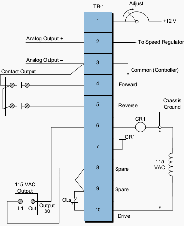
Table 1 shows the I/O address assignment table for this example, while Figure 2 illustrates the connection diagram from the PLC to the VS drive’s terminal block (TB-1). The connection uses a contact output interface to switch the forward/reverse signal, since the common must be switched.

To activate the drive, terminal TB-1-6 must receive 115 VAC to turn ON the internal relay CR1. The drive terminal block TB-1-8 supplies power to the PLC’s L1 connection to turn the drive ON. The output of the module (CR1) is connected to terminal TB-1-6. The drive’s 115 VAC signal is used to control the motor speed so that the signal is in the same circuit as the drive, avoiding the possibility of having different commons (L2) in the drive (the start/stop common is not the same as the controller’s common).

In this configuration, the motor’s overload contacts are wired to terminals TB-1-9 and TB-1-10, which are the drive’s power (L1) connection and the output interface’s L1 connection. If an overload occurs, the drive will turn OFF because the drive’s CR1 contact will not receive power from the output module.

This configuration, however, does not provide low-voltage protection, since the drive and motor will start immediately after the overloads cool off and reclose.

To have low-voltage protection, the auxiliary contact from the drive, CR1 in terminal TB-1-7, must be used as an input in the PLC, so that it seals the start/stop circuit.


I/O address assignment

Table 1 - I/O address assignment


Connection diagram from the PLC to the VS drive’s terminal block.

Figure 2 - Connection diagram from the PLC to the VS drive’s terminal block.

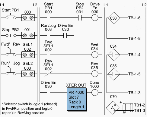
Figure 3 shows the PLC ladder program that will replace the manual operator station. The forward and reverse inputs are interlocked, so only one of them can be ON at any given time (i.e., they are mutually exclusive).

If the jog setting is selected, the motor will run at the speed set by the analog output when the start push button is depressed. The analog output connection simply allows the output to be enabled when the drive starts. Register 4000 holds the value in counts for the analog output to the drive. Internal 1000, which is used in the block transfer, indicates the completion of the instruction.

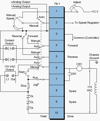
Sometimes, a VS drive requires the ability to run under automatic or manual control (AUTO/MAN). Several additional hardwired connections must be made to implement this dual control.


PLC implementation of the VS drive

Figure 3 - PLC implementation of the VS drive


The simplest and least expensive way to do this is with a selector switch (e.g., a four-pole, single-throw, single-break selector switch). With this switch, the user can select either the automatic or manual option. Figure 4 illustrates this connection.

Note that the start, stop, run/jog, potentiometer, and forward/reverse field devices shown are from the operator station. These devices are connected to the PLC interface under the same names that are used in the control program (refer to Figure 3).

If the AUTO/MAN switch is set to automatic, the PLC will control the drive; if the switch is set to manual, the manual station will control the drive.

VS drive with AUTO/MAN capability

Figure 4 - VS drive with AUTO/MAN capability


Resource: Introduction-to-PLC-Programming – www.globalautomation.info

How Motor Really Works?

$
0
0
Motor action

Figure 1 - A motor action


The basic working of a motor is based on the fact that when ‘a current carrying conductor is placed in a magnetic field, it experiences a force’.

If you take a simple DC motor, it has a current-carrying coil supported in between two permanent magnets (opposite pole facing) so that the coil can rotate freely inside. When the coil ends are connected to a DC source then the current will flow through it and it behaves like a bar magnet, as shown in Figure 1.

As the current starts flowing, the magnetic flux lines of the coil will interact with the flux lines of the permanent magnet.

This will cause a movement of the coil (Figures 1a, 1b, 1c, 1d) due to the force of attraction and repulsion between two fields. The coil will rotate until it achieves the 180° position, because now the opposite poles will be in front of each other (Figure 1e) and the force of attraction or repulsion will not exist.

The role of the commutator: The commutator brushes just reverse the polarity of DC supply connected to the coil. This will cause a change in the direction of the current of the magnetic field and start rotating the coil by another 180° (Figure 1f).

The brushes will move on like this to achieve continuous coil rotation of the motor.

Similarly, the AC motor also functions on the above principle; except here, the commutator contacts remain stationary, because AC current direction continually changes during each half-cycle (every 180°).

Resource: Practical Troubleshooting of Electrical Equipment and Control Circuits – M. Brown
(Get it from Amazon)

Direct Starting Of Squirrel-Cage Induction Motors

$
0
0
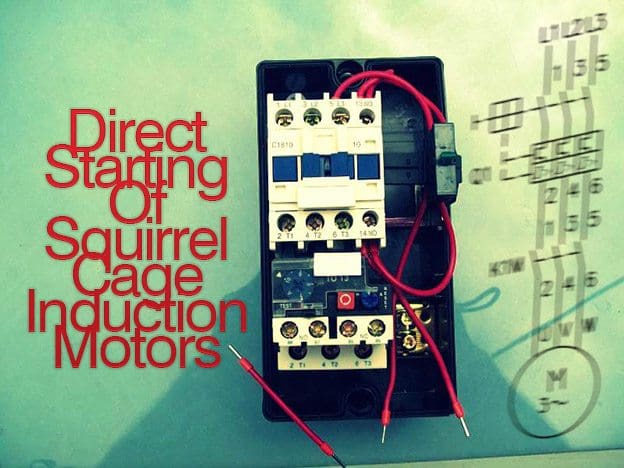
Direct Starting Of Squirrel-Cage Induction Motors

Direct Starting Of Squirrel-Cage Induction Motors

Introduction

The direct starting (Direct On Line, DOL) is the simplest and most cost-efficient method of starting a motor.

This is assuming that the power supply can easily deliver the high starting current and that the power transmission components and the working machine are suitable for the high starting torques.

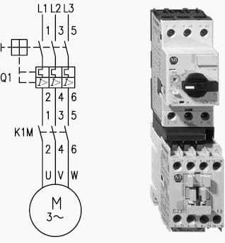
Example of a two-component starter for direct starting consisting of a motor protection circuit breaker and a contactor

Figure 1 - Example of a two-component starter for direct starting consisting of a motor protection circuit breaker and a contactor


With direct starting, the poles of contactor and motor protective device are connected to the pole conductors (Figure 1) and the operating current of the motor flows through them.

The motor protective device must therefore be adjusted to the rated operational current of the motor.

The contactor is selected according to the rated operational current Ie and the respective utilization category:
  • AC-3 Squirrel-cage induction motors: Starting, switching off during running
  • AC-4 Squirrel-cage induction motors: Starting, plugging, inching

For AC-3 operation, allowance must always be made in practice for sporadic inching operations, for example during commissioning, in case of faults or in service work.

Contactors from Rockwell Automation comply with these requirements and may be rated without risk according to AC-3 values; for the large majority of devices, the rated operational currents for the utilization categories AC-3 and AC-4 are the same. A considerable proportion of AC-4 operations or exclusive AC-4 operation is in practice relatively rare. In such cases, a high frequency of operation is often required at the same time and a high electrical life span is expected.

Thus the contactor must be selected according to these two criteria. In most cases a larger contactor must be used than would correspond to the maximum permissible AC-4 rated operational current.


Starting time

The starting time is an important parameter in starter engineering, as the starting current can be many times higher than the rated currents of motor and switchgear and correspondingly places the latter under thermal loading.

It depends on the torque of the motor and hence on the selected starting method, as well as on the torque characteristic of the load.

The difference between the motor torque and load torque is the acceleration torque. In addition to the resistive torque of the drive, the inertial mass to be accelerated has a key influence on the time taken for motor starting.

The duration of so called no-load starting, i.e. starts without loading of the drive, typically lies, depending on motor size, in the time range of under 0.1 to around 1 s, starting under load (but without large flywheel masses) up to around 5 s. For centrifuges, ball mills, calenders, transport conveyors and large fans, the start times can extend to minutes.

In the case of pumps and fans it should be noted that the pumped material (liquid, air) contributes to the effective inertial mass.

The above given approximate values apply for direct starting. The times are correspondingly extended with starter methods with reduced starting current and torque.

With respect to the permissible starting time of the respective motor, the manufacturer’s documentation is definitive.


Reversing starters

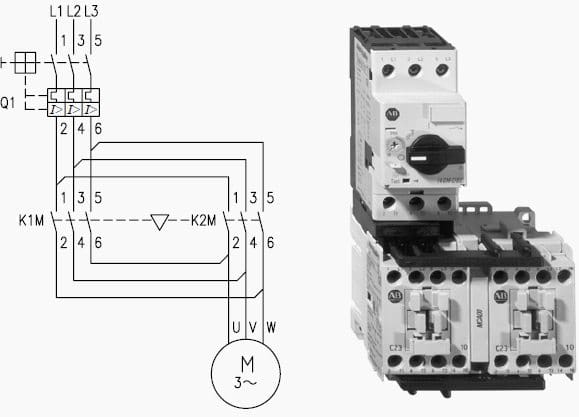
In a reversing starter the motor is switched via two contactors, one for each direction. If the motor is started from rest, the contactor is selected according to utilization category AC-3.

Often however the motor direction is changed while it is running (plugging), which means a correspondingly higher loading of the contactors and hence requires selection according to utilization category AC-4.

Reversing starter with motor protection-circuit breakers and mechanical interlock: Diagram and layout

Figure 2 - Reversing starter with motor protection-circuit breakers and mechanical interlock: Diagram and layout


Direct reversing requires a reversing delay between the contactors – for example by means of a short-term delay – of around 40 ms, to prevent short-circuits between phases. In addition to electrical interlocking of contactors of reversing starters, mechanical interlocking is recommended.

Corresponding precautions as for reversing starters are required for plugging with stopping at standstill. In this case when the motor comes to rest, the braking contactor (for example controlled by a speed sensor) is switched off and the motor is hence disconnected from the supply.


Squirrel Cage Motors (VIDEO)

Cant see this video? Click here to watch it on Youtube.

Resource: Allen Bradley – Low Voltage Switchgear and Controlgear

Torque Of Three-Phase Induction Motor Explained

$
0
0
Torque Of Three-Phase Induction Motor Explained

Torque Of Three-Phase Induction Motor Explained (photo by empoweringpumps.com)

Introduction to torque

The rotating force that a motor develops is called torque.

Due to the physical laws of inertia, where a body at rest tends to remain at rest, the amount of torque necessary to start a load (starting torque) is always much greater than the amount of torque required to maintain rotation of the load after it has achieved normal speed.

The more quickly a load must accelerate from rest to normal rotational speed, the greater must be the torque capability of the motor driver.

For very large inertia loads or loads that must be accelerated quickly, a motor having a high starting torque should be applied.

The National Electrical Manufacturers Association (NEMA) provides design letters to indicate the torque, slip, and starting characteristics of three-phase induction motors.

They are as follows:

Design A

Design A is a general-purpose design used for industrial motors. This design exhibits normal torques and full-load slip of approximately 3 percent and can be used for many types of industrial loads.


Design B

Design B is another general-purpose design used for industrial motors. This design exhibits normal torques while also having low starting current and a full-load slip of approximately 3 percent. This design also can be used for many types of industrial loads.


Design C

Design C motors are characterized by high starting torque, low starting current, and low slip. Because of its high starting torque, this design is useful for loads that are hard to start, such as reciprocating air compressors without unloader kits.


Design D

Design D motors exhibit very high starting torque, very high slip of 5 to 13 percent, and low starting current. These motors are excellent in applications such as oil field pumping jacks and punch presses with large flywheels.


Variable-torque and Constant-torque motors

Variable-torque motors exhibit a speed-torque character-istic that varies as the square of the speed.

For example, a two-speed 1800/900-rpm motor that develops 10 hp at 1800 rpm produces only 2.5 hp at 900 rpm. Variable-torque motors are often a good match for loads that have a torque requirement that varies as the square of the speed, such as blowers, fans, and centrifugal pumps.

Constant-torque motors can develop the same torque at each speed; thus power output from these motors varies directly with speed. For example, a two-speed motor rated at 10 hp at 1800 rpm would produce 5 hp at 900 rpm.

These motors are useful in applications with constant-torque requirements, such as mixers, conveyors, and positive-displacement compressors.

Induction Motor How it works? (VIDEO)

Cant see this video? Click here to watch it on Youtube.

Resource: Electrical Calculation Handbook – John M. Paschal

Starting Motor With Auto-transformer

$
0
0
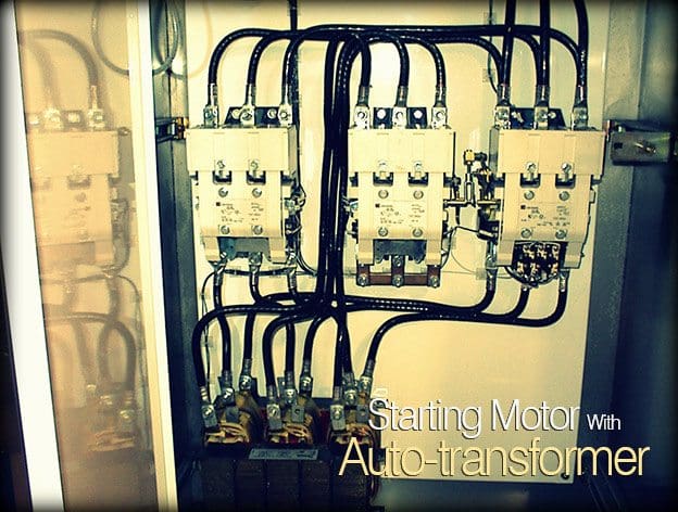
Starting Motor With Auto-transformer

Starting Motor With Auto-transformer

Circuit and function

An auto-transformer starter makes it possible to start squirrel-cage induction motors with reduced starting current, as the voltage across the motor is reduced during starting.

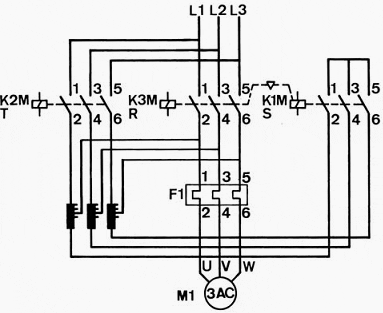
In contrast to the star-delta connection, only three motor leads and terminals are required. On starting, the motor is connected to the tappings of the auto-transformer; transformer contactor K2M and star contactor K1M are closed.

The motor starts at the voltage reduced by the transformer, with a correspondingly smaller current.

By this means the feeding current in comparison to direct starting would be reduced by the square of the transformer voltage ratio; nevertheless, it is in most cases noticeably higher, as it also covers the relatively high transformer losses.

Depending on the tapping and starting current ratio of the motor, the starting current lies at (1 … 5) · Ie. In contrast, the motor torque falls with the square of the voltage across the windings. Auto-transformers usually have three available taps in each phase (for example 80 %, 65 %, 50 %), so that the motor starting characteristic can be adjusted to the load conditions.

If the motor has reached 80 … 95 % of its rated speed (depending on the desired reduction of the current surge after switching-over), the star contactor K1M on the transformer is opened.

Now the transformer part-windings act as chokes. The motor voltage is only reduced by the chokes below the supply voltage and the motor speed does not fall. The main contactor K3M closes via auxiliary contacts of the star contactor and applies the full supply voltage to the motor.

For its part, the main contactor K3M drops out the transformer contactor K2M.

The entire procedure is thus uninterrupted.

Auto-transformer starter with uninterrupted switching over (Korndörfer starting method)

Figure 1 - Auto-transformer starter with uninterrupted switching over (Korndörfer starting method)

Rating of the starter

The main contactor K3M and the motor protective device F1 are selected according to the motor rated operational current Ie. Transformer contactor and star contactor are only briefly closed during starting.

Their rating is determined by the required contact breaking capacity, as they must reliably cope with any unforeseen disconnection during start up.

The star contactor also operates with every start-up during switching-over. The values of the rated operational currents for the transformer contactor K2M, depending on the start time and starting current, are between (0.3 … 1) · Ie, for the star contactor between (0.45 … 0.55) · Ie.


Testing Big AC Motor (VIDEO)

Cant see this video? Click here to watch it on Youtube.

Resource: Allen Bradley – Low Voltage Switchgear and Controlgear


Induction Motor Startup And Losses Calculation

$
0
0
Induction Motor Startup And Losses

Induction Motor Startup And Losses (on photo: 100 HP DISCFLO Stainless Steel Pump)

Main Objectives

The main objectives while starting an induction motor are:

  1. To handle high-starting current
  2. To achieve high-starting torque.

As we know, rotor resistance determines starting torque. Usually, this rotor resistance is small, giving small starting torque, but good running conditions. So, the squirrel-cage motor can run only with low-starting loads.

If the rotor resistance is increased by some means, then the slip and speed at which maximum torque occurs can be shifted. For that purpose, external resistance can be introduced in the rotor circuit, which is done inthe case of slip ring or wound rotor type motors.

When power is applied to a stationary rotor, excessive current will start flowing.
This happens due to the fact that there is a transformer action between the stator winding and the rotor winding, and the rotor conductors are short-circuited. This causes heavy current flow through the rotor. If, for reducing this heavy starting current, starting voltage applied is reduced then it affects the starting torque as well.

Methods of Starting the Motor

To get everything out, the following method of starting is generally used:

  1. DOL starting
  2. Auto transformer starting
  3. Star–delta starting.


Losses Calculation

The following are the losses in an induction motor:

  1. Core loss in the stator and the rotor
  2. Stator and rotor copper losses
  3. Friction and windage loss.

Core loss is due to the main and leakage fluxes. As the voltage is assumed constant, the core loss can also be approximated as a constant. DC can measure the stator resistance. The hysteresis and eddy current loss in the conductors increase the resistance, and the effective resistance is taken at 1.2 times the DC resistance.

The rotor copper loss is calculated by subtracting the stator copper loss from the total measured loss or the rotor I2R loss. The friction and windage loss may be assumed constant, irrespective of the load.

Efficiency = Rotor output/stator input
Output = Input – Losses

Example With Calculations

Consider a three-phase 440 V, 50 Hz, six-pole induction motor. The motor takes 50 kW at 960 rpm for a certain load. Assume stator losses of 1 kW and friction and windage loss of 1.5 kW.

To determine the percentage slip, rotor copper loss, rotor output, and efficiency of the motor, perform the following function:

Percentage slip

The synchronous speed of the motor = (50 ×120) / 6 = 6000 / 6 = 1000 rpm
Slip = (Synchronous speed – Actual speed) = 1000 – 960 = 40 rpm
Percentage slip = [(40 / 1000) × 100] = 4% = 0.04

Rotor copper loss

Rotor input = 50 1 = 49 kW
Rotor copper loss = Rotor input × Slip = 49 × 0.04 = 1.96 kW

Rotor output

Rotor output = Rotor input – Rotor copper loss – Friction and Windage loss
= 49 – 1.96 + 1.5
= 49 – 3.46
= 45.54 kW

Motor efficiency

Motor efficiency = Rotor output/Motor input
= 45.54 / 50 = 0.9108
= 91.08%


Century Electric Repulsion Start Induction Motor (VIDEO)

Cant see this video? Click here to watch it on Youtube.

Resource: Practical Troubleshooting of Electrical Equipment and Control Circuits – Mark Brown, Jawahar Rawtani and Dinesh Patil (Get it from Amazon)

How to determine motor torque & speed requirements

$
0
0
How to determine motor torque and speed requirements

How to determine motor torque and speed requirements

Operating Speed Range

The desired speed range may be difficult to achieve depending on the type of application. In general, depending on motor size and load type, very wide ranges may require a special motor.

Operation at very low speeds, requiring the motor to run at very low frequency (below approximately 6 Hz) or very high speeds requiring the motor to run at very high frequencies (above 90 Hz) may require a special motor.

Motor synchronous speed varies directly with the control output frequency. Therefore, the frequency required to achieve a desired application speed can be approximated by dividing the desired speed by the motor rated speed and then multiplying by the rated frequency of the motor.

If the minimum or maximum frequency are near or outside the limits mentioned above then the motor manufacturer should be consulted before proceeding.

Examples of speed ranges are listed below, expressed as a ratio of the motor base speed to a minimum speed.

Constant and Variable Torque Speed Range Examples
(Base speed = 2500 RPM)

Minimum Speed (RPM)% Motor Base SpeedSpeed Range Ratio
1250502:1
625254:1
2501010:1
125520:1
251100:1

Constant horsepower applications have a speed range where the base speed is the lowest speed not the
top speed.

Constant Horsepower Speed Range Examples
(Base speed = 2500 RPM)

Minimum Speed (RPM)% Motor Base SpeedSpeed Range Ratio
37501501.5:1
50002002:1
75003003:1

Note: These speed range examples are for illustration purposes only. Not all motors will be capable of operating withinthese ranges.


Breakaway Torque

The motor must have enough breakaway torque to start the load.

This is not related to the motor locked rotor or starting torque published for across-the-line starting. Breakaway torque is limited by the motor, the available current from the control, and by the setup of the control.

If the static torque required to start the load moving is above 140 percent of motor full-load torque, an oversized control and a motor with sufficient torque capability may be required.

There are several techniques that can be used to achieve the required torque, within the capability of the components used. These techniques should be discussed with the motor manufacturer to achieve the optimum configuration.

Resource: NEMA VSD Guide

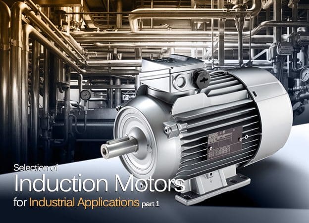
Selection of Induction Motors for Industrial Applications (part 1)

$
0
0
Selection of Induction Motors for Industrial Applications

Selection of Induction Motors for Industrial Applications (photo by http://www.iecee.org)

Introduction

All types of industries are invariably required to install different types of electric motors as prime mover for driving process equipment participating in their respective production line up. The continuous process of technical development has resulted into availability of highly diversified types of electric motors.

Hence, an utmost care should be exercised in selection of most appropriate type of motor considering number of technical factors for each application, so that the motor would provide desired and optimum performance.

The characteristics of motors vary widely with the nature of their application and the type of duty they are expected to perform. For example, the applications like constant speed, constant torque, variable speed, continuous/intermittent duty, steep/sudden starts, frequent start/stops, etc. should be taken into consideration carefully when deciding for the type of a motor for that specific application.

Moreover, the motors are required to perform quite often under abnormal conditions during their total service life.

In view of above, an incorrect selection of motor always lands the industrial buyer into all sorts of problems, including premature failure of the motor, causing severe production curtailments.

Like one mentioned above, a number of other factors and design features like weather conditions, stringent system conditions, abnormal surroundings, hazardous area, duty cycle, motor efficiency, etc. should be considered while deciding the rating and subsequently drawing out the technical specifications of the motor.

Stator and Rotor Damages

Stator and Rotor Damages

Abnormal conditions and effects

The usual abnormal conditions encountered by the motors are given below.

1. Abnormal System Conditions

  1. Voltage
    1. Undervoltage
    2. Overvoltage
    3. Unbalance in 3-phase
    4. Single phasing
    5. Voltage surges
  2. Frequency
    1. Low frequency
    2. High frequency

2. Abnormal Operating conditions

  1. Locked rotor or stalled rotor
  2. Reswitching/Frequent start-stops
  3. Momentary interruption/Bus transfer
  4. Overloading
  5. Improper cable sizing

3. Environmental conditions

  1. High/low ambienttemperature
  2. High altitude
  3. High humidity
  4. Corrosive atmosphere
  5. Hazardous atmosphere/surroundings
  6. Exposure to steam/salt-laden air/oil vapour

4. Mechanical problems

  1. Seized bearings
  2. Incorrect alignment/foundation levelling
  3. Incorrect fixing of coupling
  4. High vibration mounting
  5. External shock due to load

5. Condition at location

  1. Poor ventilation
  2. Dirt accumulation
  3. Exposure to direct sunlight

Though, above mentioned abnormalities may prevail for short or long duration or may be transient in nature, major impact of the listed abnormal conditions is overheating of the motor along with one or several of the other effects as follows.

Change in the motor performance characteristics like drawl of more power and consequent deterioration in motor efficiency, etc.

Increase in mechanical stresses leading to:

  1. Shearing of shafts
  2. Damage to winding overhang
  3. Bearing failures
  4. Insulation failures

Increase in stator and rotor winding temperature leading to:

  1. Premature failure of stator or rotor insulation (For wound rotor motor)
  2. Increased fire hazard
  3. Breakage of rotor bar and/or end ring (For squirrel cage motors)

All the motors encounter few or several of these abnormalities during the course of their service lives. Consideration of listed abnormal conditions at design stage greatly helps to minimise the effects of abnormal conditions to maintain a consistent performance.


Design Considerations

Following are the most important design factors required to be considered when selecting a motor for any of the diversified industrial applications.

Output in kW/HP

There are two principle limitations for selecting the motor output:

1. Mechanical limitation

The breakdown torque, which is the maximum torque that the motor can produce when operating without stalling. This is a critical design factor in motor applications, particularly for the motors subjected to occasional extreme load conditions.

Another critical factor is the locked-rotor torque, which is the maximum torque that the motor can produce during startup from steady-state condition, a critical design feature for conveyor drives.

2. Electrical limitation due to insulation provided on the motor windings

The electrical load on the motor can be imposed till the winding insulation is able to withstand the prescribed temperature rise over an ambient for that particular class of insulation. Life of the motor greatly depends on the temperature rise of the windings.

Anticipated life-span of the motor can be achieved provided it is operated at its rated output without overloading and the prescribed preventive maintenance practices are religiously followed.

Speed of the Motor

Most of the motors are directly coupled with the driven equipment where in the speed of the motor and the driven equipment will be same.

In order to meet the speed of the driven equipment, the devices like gearbox, chains or belts are introduced between motor and driven equipment. In this case, it may be necessary to provide the rotor shaft suitable for its attachment with the speed decreasing or increasing device and hence the specification should include such specific requirement.

In case a variable speed drive is to be used for the speed variation, the motor should be compatible for this specific application. The standard motor may not provide desired performance when operated via variable speed drive.

Cant see this video? Click here to watch it on Youtube.


Power Supply Voltage and Frequency Variations

Variations in the power supply parameters, i.e. voltage and frequency significantly affect overall performance of the motor. As provided in IS:325-1996, the permissible voltage variation is ±5 to ±10%, permissible frequency is 50Hz ± 3%, and permissible combined variation is ±6 %.

The effect of undervoltage is more serious than that of overvoltage.

The higher torque, resulting from overvoltage, can handle a little overload without undue heating of the winding, but only for a short duration. Continuous operation with undervoltage condition increases the current at the rate of about 20% for every 5% reduction in the supply voltage, increasing the rated copper loss.

This results into heating and prolonged temperature rise, and finally the burning of winding. During a motor start-up, the torque reduces by 10% for each 5% reduction in the supply voltage, causing more starting current and consequently more rapid heating of the
winding.

Large burned out induction motor

Large burned out induction motor


The motor offers reduced efficiency at either overvoltage or undervoltage. Power factor drops sharply with higher voltage and improves with lower voltage. Even when motor is lightly loaded, over-voltage cause rise in current and temperature thus reducing the life of motor. The variation in frequency by +5 % decreases the torque by about 10% and vice-versa at – 5% frequency, the torque increases by about 10%.

It is, therefore, of utmost importance to consider the combined effect of variation in voltage and frequency both when purchasing the motor.

Unbalance in the supply voltage results into a current unbalance of 6 to 10 times the percentage voltage unbalance. This in turn results into generation of negative sequence currents in the rotor causing its overheating and premature failure.

It is therefore vital to specify the permissible limits of variations in the power supply parameters for the motor in accordance with the requirement of the driven equipment. However, the permissible limits should never be more than provided in the applicable Indian Standard IS:325-1996 (Reaffirmed in 2002).

Will be continued very soon…

Selection of Induction Motors for Industrial Applications (part 2)

$
0
0
Selection of Induction Motors for Industrial Applications (part 2) - photo by TCD Systems

Selection of Induction Motors for Industrial Applications (part 2) - photo by TCD Systems


Continued from first part: Selection of Induction Motors for Industrial Applications (part 1)


Design Considerations (cont.)

Motor Efficiency

The new IEC 60034-30 motor efficiency standard

The new IEC 60034-30 motor efficiency standard could have major energy-saving impact for industrial motors worldwide.


Though standard motors are now available with a better efficiency, this factor (motor efficency) requires due attention when making the selection of the motor for a specific application in view of substantial quantum of power consumed by the motors in the industries.

The motors running continuously should be as efficient as possible to reduce the power consumption.

Improvement of even 1% in efficiency results into saving of enormous quantum of power over a life span of the motor as well as the cost of power.

For the drives to be in service round the clock, due consideration should be given install the energy efficient motors having EFF 1 or EFF 2 class even at the higher cost, as the premium paid in the form of capital investment will be paid backhand somely in the form of cost saving due to significant energy saving when the drive will be kept in continuous service.


Ambient Temperature

As per normal standards, the motor output is given by the vendors based on 40°C ambient temperature.

If ambient temperature is expected to be high for a longer duration, then the motor is required to be checked for its suitability to maintain the specified output at higher temperature, or otherwise, the deration factor is to be applied to know the actual anticipated output at higher temperature.

In order to maintain the motor output at higher temperature as per the power requirement of driven equipment, it may be necessary that the motor with a higher frame size for the same rating is selected to avoid adverse effect of derating.


Altitude

The standard motor outputs are specified by the manufacturers for site altitude up to 1000 m.

For altitudes of more than 1000 m, the motor ratingis required to be checked for its suitability to maintain the specified output, or otherwise the duration factor is to be applied to know actual anticipated output at higher altitude. Criteria for the selection of motor remains the same as provided for higher ambient temperature.


Method of Starting and Number of Starts

DOL starter, with enclosure, less overload, contains TeSys Model D contactor

DOL starter, with enclosure, less overload, contains TeSys Model D contactor (Ratings: 4kW, 9A, AC3, 240V, less O/L)

The starting performance of the motor depends on the method of starting deployed, i.e. directon-line, star-delta, high resistance, auto transformer, variable frequency drive, etc.

The direct-on-line starting (DOL motor starter) is the most common method adopted in which the starting current is 6-7 times the rated full load current of the motor. For high starting torque, the direct-on-line starting is essential. If the motor driving a load requiring high starting torque is started using star-delta starting, either the speed may not pick-up affecting the motor acceleration, or may take a very long time to come up to its rated speed under loaded condition inducing severe electrical and mechanical stresses respectively in the winding and core.

Where the starting torque requirement is not so critical, the star-delta starting or any other reduced voltage method of starting is used.

Where the starting with very heavy load, such as with hoist or crane drives, and speed control over a wide range is required, it is advantageous to consider the slip-ring type (or wound rotor type) motor with a drum controller starter or resistance starter.

As per modern day technology, a soft starter can also be considered for such applications.

It is essential to specify anticipated number of starts per hour or per shift of 8-hrs duration as well as number of consecutive starts required when the motor is started from cold or hot condition for facilitating the design of motor windings and selection of correct class of insulation to encounter anticipated temperature rise due to number of starts.

Large rated motors are often started via soft starters. It is desirable to explicitly specify this requirement so that the motor, compatible for such application, is designed and manufactured.


Duty Cycle

Lafert Electric motor that combines brushless permanent magnet (PM) and AC induction motor technologies.

Lafert Electric motor that combines brushless permanent magnet (PM) and AC induction motor technologies.

Selecting the proper electric motor also depends on whether the load is steady, variable over a fixed time duration, following a repetitive cycle of variation, or load with pulsating torque or shocks. The motors to be kept min service round the clock, such as driving pumps, fans, etc., may be selected on the basis of continuous load and other factors discussed in this article.

This is the Duty Cycle required to be performed by the motor.

The motors driving the equipment like automatically controlled compressors, cranes, hoists start and stop a number of times per hour and those in some machine tools start and stop many times per minute.

The Duty Cycle is a fixed repetitive load pattern over a given period of time which is expressed as the ratio of on-time to cycle period. When operating cycle is such that electric motors operate at idle or a reduced load for more than 25% of the time, Duty Cycle becomes a factor in sizing electric motors. Also, energy required to start electric motors (that is, accelerating the inertia of the electric motor as well as the driven load) is much higher than for steady-state operation, so frequent starting could overheat the electric motor.

When the motor is supposed to operated at idle or reduced load for more than 25% of the time in accordance with its operating cycle, the Duty Cycle becomes a vital factor in sizing the motor.

Also, the energy required to start the motors, i.e. during accelerating along with driven load, is much higher than that required for steady-state operation, so frequent starting, in most probability, is likely to overheat the motor.


Insulation Class

The permissible temperature rise for six insulation classes is based on the ambient temperature of 40°C as shown in following table for different class of insulating materials.

Thermal Class of InsulationNormal permissible temp. rise over 40°CNormal total temp. °CMaximum permissible temp. rise °CInsulating materials
A60100105Cotton, Silk, Impregnated/Coated paper
E75115120Synthetic enamel based on polyvinyl
acetate, Polyurethane, Epoxy on polyamide resin
B80120130Mica, Glass fibre, Asbestos with suitable
bond, viz. Synthetic resin varnishes, Epoxy resin shellac, Asphalt or bituminous compounds
F100140155Mica, Glass fibre, Asbestos with suitable bond, viz. Alkyd epoxy resin, add silicon alkyd resin
H125165180Silicon elastomers, Mica, Glass fibre, etc. with bonding substances like silicon resins
G170210225Mica porcelain, Other mica class quartz, with bonding materials of silicon resin

It may be remembered that for every 10°C rise in operating temperature, the insulation life reduces by 50% of its usual life.

Thus the temperature rise in motor is usually the dominating ageing factor of influence on the winding insulating materials and insulation systems. Hence it is essential to specify proper class of insulation for the motor based on design ambient temperature, if it is more than standard design temperature of 40°C.

The endurance of the insulation is adversely affected by many other ageing factors, such as surroundings, electrical and mechanical stresses, vibration, deleterious atmospheres and chemicals, moisture, dirt and radiation.

Will be continued very soon…

Selection of Induction Motors for Industrial Applications (part 3)

$
0
0
Selection of Induction Motors for Industrial Applications (part 3)

Selection of Induction Motors for Industrial Applications (photo by ABB)


Continued from first part: Selection of Induction Motors for Industrial Applications (part 2)


Design Considerations (cont.)

Different Rotor Classes

The different rotor class, i.e. KL7, KL10, KL13, KL16, KLp, etc. are available in case of the motor to fulfil the functional torque requirements of the driven equipment. The rotor classes indicate against what quantum of the load torque the motor would be able to start easily.

The motor with KL10 class of rotor, when started direct-on-line, would accelerate safely to its rated speed against the load torque of 100 % of its rated torque. Similarly, the motor with KL16 class of rotor would be capable of starting against the load torque of 160 % of its rated torque.

Though, KL10 class rotor could take maximum starting torque up to 180 % of the full load torque, and for KL16 class, it could go up to 200 %, but for very minimum time exerting more stress to the rotor.

Such practice reduces the motor life in no uncertain terms.

It is therefore essential to obtain the technical data for the torque requirement of driven equipment during starting and incorporate in the specification so that the motor of correct rotor class will be installed.


Constructional features of motor

Based on the application requirements, the constructional features of the motor are to be selected as follows:


Mounting Arrangement

Different types of mounting arrangement for the motors are Horizontal foot mounted (B3), Horizontal flange mounted (B5), Flange-cum-foot mounted (B3/B5), Vertical flange mounted with shaft downwards (V3), etc and so on.

International standards specify mounting arrangement with some different notation.

It is important to specify correct mounting arrangement for satisfactory installation of motor and its coupling with the driven equipment. Details of driven equipment may also be furnished if desired by the motor vendor.


Enclosures

The enclosures are classified under two categories as follows. It is selected based on the specific application and location of the motor.

Open TypeTotally Enclosed Type
 1. Screen protected drip proof (SPDP) 1. Totally enclosed fan cooled (TEFC)
 2. Splash waterproof 2. Totally enclosed surface cooled
 3. Pipe ventilated 3. Totally enclosed pipe ventilated
 4. Weather protected 4. Hose and splash proof
 5. Increased safety motor with enclosure ‘e’ for hazardous areas
 6. Totally enclosed for marine applications

Frame size

General Electric triclad induction motor frame

General Electric triclad induction motor frame


The frame size of the motor is to be selected considering ambient conditions and environment in surroundings, where it is to be installed.

If the ambient temperature is expected to be abnormally high, the motor with one higher frame size for the same rating provides better services due to availability of more cooling surface area due to higher frame size. This factor is thus related to location of the motor.


Mechanical design features

Coupling Arrangement with Load

Motor directly coupling

Motor directly coupling


It is necessary to mention whether the motor is to be directly coupled with the driven equipment, or coupled through a belt/chain drive, or gearbox.

For belt-drives, the motor shaft diameter and length depend on the type of belt and pulley, as the standard shaft length suitable for flat belt may not be suitable for V-belt drive and width of pulley. It is necessary to specify the shaft extension requirement.


Type of Driven Equipment

For better selection of motor, it is necessary to specify the type of driven equipment, viz., centrifugal pump, compressor, blower, bowl mill, conveyor drive, etc.

The moment of inertia and accelerating torque of the driven equipment along with its duty cycle should also be specified to consider starting time of the motor and anticipated temperature rise during starting.

The design of windings would greatly depend on this technical data.


Terminal Box

Motor terminal box

Motor terminal box

The size of cable with number of cores should be specified so as to enable the motor manufacturer to provide correct type and size of cable terminal box. When a number of parallel cables are to be terminated, as in case of star-delta started motor, a special terminal box with a modified arrangement may be specified to facilitate the cable termination.

If required, the cable splitter box should also be specified along with the main terminal box for facilitating splitting of cable cores before termination.

Where the space heater is provided in the motor, itis desirable that the leads of space heater are brought out in a separate terminal box so as to avoid unnecessary congestion of cables in the main terminal box.

Moreover, it is essential to specify whether the terminal box should be located on side or on the top of the motor considering anticipated encroachments at site due to structures, pipelines, etc. around location of motor. Depending on the site location, it may be necessary to specify Degree of Protection required for the terminal box.

It is general practice to maintain same Degree of Protection for the motor and terminal box.


Earthing Terminals

In accordance with the Indian standard specification, two separate and distinct earthing terminals should be essentially provided on the body of the motor and one earthing terminal should be provided internal in the cable termination box is to be provided.

Additionally, one earthing terminal may also be provided on either one side of the terminal box housing or internal in the terminal box housing for enhancing overall safety of the equipment.


Location data

Hazardous Area Motors - Explosion Proof & Purged and Pressurized

Hazardous Area Motors - Explosion Proof & Purged and Pressurized


It is essential to include all the possible details of location and surroundings in the technical specification.

The motor with a suitable enclosure should be selected based on its location, whether it is indoor, outdoor, semi-outdoor, prone to dust, corrosive vapours, chemically hazardous explosive area, salt laden air, etc.

Corrosive chemical vapours attacks not only the motor winding insulation, but also the housing, stator laminations, rotor, shaft and bearings. For the motors working in the corrosive areas, the winding should be applied a specific varnished impregnation treatment, anti-acidic treatment and overhangs should be applied with epoxy based varnish.

Corrosion to metal body is prevented by applying epoxy based resin paint.


Service factor or overload capacity

The service factor of a motor indicates how much it could be overloaded without immediately failing. Generally, the motors are designed with 1.15 service factor with the development of high quality insulating materials that can withstand higher temperatures.

Most of the motors do not operate at maximum efficiency when overloaded. The optimum efficiency is obtained from the standard motors when operated at around 80 to 95% of their rating and the energy efficient motors offer optimum efficiency when operated between 65% to 95% of their rating.

Although the motors operating between their full load rating and their service factor rating do not fail immediately, their service life certainly becomes shorter.

Hence, it is best to avoid designing of motors to operate with overload except for short time duration, even if permitted by the service factor. A high service factor can be used as an indication of a high quality, more reliable motor.

Conclusion

Effort made in technical article covers as many factors for selection of motor as possible, through the subject is vast. The complete technical specification would greatly facilitate the motor vendor to propose a type of motor required for a specific application.

Effective selection and application of modern day electric motors require a thorough technical and practical knowledge of basics of rotating machines as well as an in-depth awareness of the latest technical developments via continuous contact.

Operating conditions such as duty cycle, number of starts, ambient conditions, and data for location, environment, driven equipment, etc. are important considerations for the motor efficiency and reliability. It is also imperative to seek advice of the motor manufacturer many a times if motor will be operated under any unusual service conditions to support the selection procedure.

High-speed operation with the new synchronous reluctance motors

High-speed operation with the new synchronous reluctance motors can eliminate use of mechanical power transmission elements such as gearboxes in some applications.

It can also be seen from the above discussion that most of the technical requirements are interwoven and closely related with each other. Consideration of one factor may affect the other factor and hence it is important to adopt an integrated approach to the total specification.

Finally, the number of specific requirements is going to raise the cost of the motor.

For example, the initial cost of high efficiency motor will be more, depending on design and specific material aspects, but the consistent lower operating cost due to less drawl of power will prove economically beneficial in a long run. Besides considering various general design features as mentioned above, the specific requirements in view of abnormal site conditions and application requirements must be considered and brought out in the purchase specification.

The extra cost, required to be incurred for some specific features, would simplify the maintenance to such an extent that the repayment would be in a shortest duration with reduced outage of the motors.

Last but not least, the selection and application of electric motors has become more complex than ever before because of the emergence of high efficiency and premium efficiency (PE) motors as a part of continuous process of technical developments. As a result, one must extremely careful look to any application of the electric motor.

Three phenomenons in the iron of AC machines

$
0
0
Three phenomenons in the iron of AC machines

Three phenomenons in the iron of AC machines

Magnetic Circuits

Most of our practical AC machines (motors, generators ad transformers) depend heavily on the magnetic field for operation. The core iron of the machine provides a path for the magnet field.

There are a number of phenomena in the iron that are of interest as the terms keep coming up in following article.


1. Eddy Currents

Eddy currents are electrical currents that flow in the core iron of an AC machine. To generate voltages in takes a magnetic field, conductors and some change between them.

In an AC machine the magnetic field is always in phase with the current, it is continuously changing.

The iron is a conductor and voltages will be induced into the iron and current will flow. The induced voltages are low but the currents can be high. The current flow will heat the iron.

If steps are not taken in machine construction cores would get extremely hot and the power loss would be huge. The core of a practical AC machine is made of thinsheets of metal. The sheets break up the circulating path and the eddy currents are minimized.


2. Hysteresis

Fig. 3.2 Magnetization and hysteresis curves

Fig. 3.2 Magnetization and hysteresis curves


Hysteresis is a phenomenon that occurs in core iron. It takes a certain amount of energy to magnetize iron.

The magnetic dipoles of the iron must be aligned. The external magnetic field acts on the dipoles and forces then to align. In an ac corethe dipoles are continuously being realigned so there is a continuous energy loss in the core.

This loss shows up as heat in the core. Hysteresis losses are minimized by the use of steel that is easy to magnetize.

Hysteresis and eddy currents always occur together. Like Bert and Ernie or beach and beer they are inseparable. Both are a result of the changing magnetic field in the core and both cause heating in the core. In the terminology of AC machines together they make up the core losses. Part of the power input into any AC machine shows up as heat in the core and is an inefficiency of the machine.


3. Magnetic Saturation

Most electrical machines depend on a magnetic circuit. This circuit is invariable made of iron with properties that make it easy to change the magnitude and direction of the field in the core.

One of the limiting characteristics of a magnetic circuit is the saturation of the iron with the magnetic field.

The magnetic field is generated by passing current through a coil that somehow wrapped around an iron core. As the current in the coil increases, the magnetic field in the core increases. Initially this is a fairly proportional relationship. Double the current and you double the field.

However, the core eventually becomes saturated with the magnetic field and it becomes harder and harder to increase the field strength so it takes more and more current.

The relationship between field strength and current changes from one where relative small changes in magnetic field cause large changes in magnetic field to one where it takes large changes in current to get small changes in magnetic field.

Typical Saturation Curve

Figure 1 - Typical Saturation Curve


Most electrical equipment is designed to run below the saturation region and moving into the saturation region has negative consequences. Most of our machines (transformers, generators & motors) are alternating current machines and depend on induced voltages in the windings for their operation.

The induced voltages are dependant on the rate of change ofthe magnetic field in the core. The relationship between the magnetic field and induced voltage is captured in Faraday’s Law:

Faraday's Law formula

Where:

e – induced voltage
N – the number of turns in the coil
Φ - magnetic field
t – time

In an AC machine the flux voltage and frequency are all related. If the system voltage increases at a given frequency the magnetic field strength in the machines must increase. If the frequency (related to the rate of change of flux) drops the magnetic field must increase to maintain a fixed voltage.

Most machines are designed to run with the magnetic field strength just below saturation. An increase of field in the neighbor hood of 10% will cause the core to go into saturation. A saturated core requires large amounts of magnetizing current. Large currents will cause large I2R heating in the windings.

In an AC machine the core is heated by the continuously changing magnetic field. The continuous changing field produces eddy currents and hysteresis losses in the core. Eddy currents are electrical currents produced in the core iron itself. They heat the iron by electrical heating. Hysteresis losses are losses internal to the iron and are related to the forces required to change the direction and magnitude of the field in the core.

They are magnetic heating effects. In a situation where the magnitude of the magnetic field increases so will the heating effects of eddy currents and hysteresis.

Reference: Science and Reactor Fundamentals and Electrical CNSC Technical Training Group

Split-phase motors for medium-duty applications

$
0
0
Split-phase motors for medium-duty applications

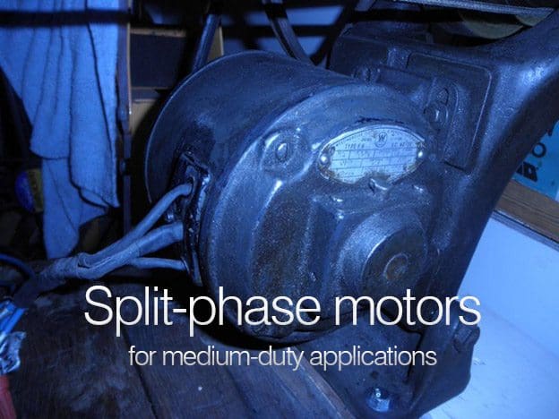
Split-phase motors for medium-duty applications (photo by MikeC5 at practicalmachinist.com)

Starting winding in series with a centrifugal switch

The split-phase (SP), or more accurately, the resistance-start, split-phase, induction run motor,is recommended for medium-duty applications.

It can run at constant speed even under varying load conditions where moderate torque is acceptable. Split-phase motors have squirrel-cage rotors and both a main or running winding and a starting or auxiliary winding.

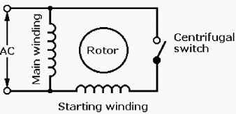
The schematic diagram for an SP motor, Figure 1, shows the starting winding in series with a centrifugal switch and the main winding in parallel across the AC line. The starting winding is wound with fewer turns of smaller-diameter, higher-resistance wire than the main winding.

Figure 1 - Single-phase motor - Resistance start split-phase motor

Figure 1 - Single-phase motor - Resistance start split-phase motor


When energized, current flowing in the starting winding is essentially in phase with the line voltage, but current flowing in the parallel main winding lags behind line voltage because it has lower resistance and higher reactance. This lag “splits” the single phase of the AC line by introducing about a 30° electrical phase difference between the currents in the two windings.

Although it is small, this phase difference is enough to provide a weak rotating magnetic field which interacts with the rotor, causing it to rotate.

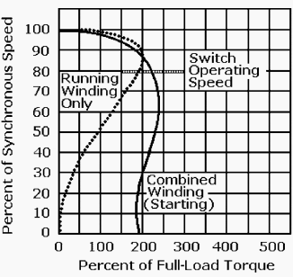
The typical torque-speed curves for an SP motor, Figure 2, show that starting current is high and running torque is moderate When rotor speed reaches about 80 percent of its rated full-load synchronous speed, its built-in automatic centrifugal switch disconnects the starting winding, protecting it from destructive overload.

Speed-torque curves for a typical split-phase motor

Figure 2 - Speed-torque curves for a typical split-phase motor


The SP motor then continues to run on the single oscillating AC field established by its main winding. SP motors are rated from 1/20 to 1/3 hp when operating from a 120/240-V AC line, and full-load speed is from 865 to 3450 rpm.

These motors are recommended for applications where motor stops and starts are frequent. SP motors are used to drive fans, blowers, pumps, office machines, and power tools where the load is applied after the motor has reached its operating speed.

Reference: Handbook of electrical design details – Neil Sclater, J. E. Traister
(Get this book from Amazon)


Few Words About Capacitor-Start (CS) Motors

$
0
0
Start-run capacitor single-phase induction motor

Start-run capacitor single-phase induction motor (Source ABB)


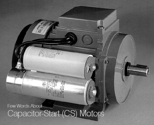
The capacitor-start (CS), or more precisely, capacitor-start, induction-run motor, is a modified split-phase induction motor used for hard-to-start loads. CS motors are efficient and require starting currents about 5 times their full-load currents.

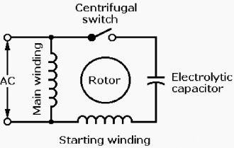
The schematic Figure 1 shows that the CS motor circuit is the same as the SP motor circuit, except that it includes a centrifugal starting switch and a small-value AC electrolytic capacitor in series with its starting winding.

Single-phase motors - Capacitor start

Figure 1 - Single-phase motors - Capacitor start


The typical torque–speed curves for a CS motor, Figure 2, show that it provides about twice the starting torque of an SP motor. The capacitor lowers the motor’s starting current and increases the phase difference between currents in the running and starting windings to 90°.
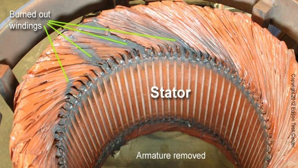
(This is about 60° more than the phase difference in SP motors.)

Speed–torque curves for a typical capacitor-start motor

Figure 2 - Speed–torque curves for a typical capacitor-start motor


The capacitor functions only when the CS motor is started, so it can be relatively small and inexpensive. Both the starting winding and capacitor are disconnected by the centrifugal starting switch when the CS motor reaches about 80 percent of its running speed.

The motor then continues to run with only its main winding energized.

CS motors are rated from 1/8 to 3/4 HP.

They run at constant speed under varying loads, offer high running and starting torques, and high overload capacity. Their range of full-load synchronous speeds matches that of SP motors—865 to 3450 rpm when powered from a 120/240-V AC line.

CS motors are used to drive machine tools, refrigerator and air-conditioning compressors, conveyors, pumps, blowers, and fans.

The major components of a fan-cooled CS motor are identified in the exploded view Fig. 10-6. The capacitor in this motor is mounted outside the motor frame in a removable protective housing, to make it easier to replace if necessary.


Replacing a Motor Start Capacitor (VIDEO)

Cant see this video? Click here to watch it on Youtube.

Reference: Handbook of electrical design details – Neil Sclater, J. E. Traister
(Get this book from Amazon)

Keeping Motor At Correct Temperature When Connected To a Frequency Converter

$
0
0
Keeping Motor At Correct Temperature When Connected To a Frequency Converter

Keeping Motor At Correct Temperature When Connected To a Frequency Converter (photo by Yaconto LLC.)

Two types of influence

When a motor is connected to a frequency converter it must be kept at the correct temperature, and this is subject to two types of influence:

  1. If the speed decreases, the cooling air volume goes down.
  2. If a non-sinusoidal motor current is present, more heat is generated in the motor.
At low speeds the motor fan is not able to supply enough air for cooling. This problem arises if the load torque is constant throughout the control range.

This lower ventilation determines the level of torque allowed during continuous loads.
The need for external ventilation for a motor at rated size and an oversize motor

Figure 1 - The need for external ventilation for a motor at rated size and an oversize motor


If the motor runs continuously – at 100% rated torque – at a speed which is less than half the rated speed, the motor requires extra air for cooling (the grey areas in Figure 1).

Alternatively the load ratio of the motor can be reduced by selecting a bigger motor. However, care must be taken not to oversize the motor too much for a given frequency converter.

If the motor current is not sinusoidal, it should not be subjected to 100% load all the time as it will receive harmonic currents that increase its temperature. The size of the harmonic currents determines the amount of heat.
A non-sinusoidal current generates extra heat in the motor

Figure 2 - A non-sinusoidal current generates extra heat in the motor


Reference: Fact Worth Knowing about Frequency Converters – Danfoss

What is the rewind scenario if a motor fails?

$
0
0
What is the rewind scenario if a motor fails?

What is the rewind scenario if a motor fails? (photo by electricmotorsales.co.uk)

Increasing Motor Efficency

Unlike an initial motor purchase where your decision is limited to procuring a standard versus a premium efficiency motor, a motor failure or burnout produces three alternatives. Your options are to rewind the failed motor, purchase a new standard-efficiency motor, or purchase an energy-efficient replacement motor.
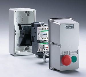
For this scenario, motor installation labor costs are again not included as the existing motor must be removed and reinstalled anyway.

50 HP Emergency Motor Rewind - Seized motor under repair

50 HP Emergency Motor Rewind - Seized motor under repair


Assuming that the failed motor can be rewound, the baseline or lowest initial cost approach is to rewind the motor to its original specifications. As some older U-Frame motors were built with oversized slots, it is sometimes possible to perform a “high-efficiency” rewind and slightly increase the efficiency of the motor by adding more copper to reduce I2R losses.

If the original unit was wound with aluminum wire, it should be replaced with copper.

A motor should be rewound with the same (or larger) winding wire size and configuration. If a repair shop does not have the correct wire size in stock and uses a smaller diameter wire, stator I2R losses will increase.

While a decrease in the number of turns in a stator winding reduces the winding resistance, it also shifts the point at which the motor’s peak efficiency occurs toward higher loads and increases the motor’s mag-netic field, starting current, locked rotor, and maximum torque. A change from 10 to 9 turns will increase the starting current by 23 percent, which can cause problems in the electrical distribution and motor protection systems.

In a typical rewind, the stator is heated to a temperature high enough to bum out its winding insulation. The windings are then removed and replaced.

In the past, many rewind shops emphasized speed High temperatures were used to shorten repair times and get the motor back in service quickly. Hand-held torches were sometimes used to soften varnish for easier coil removal.

The resulting higher temperatures increase losses by changing the electrical characteristics of the motor’s core.

For both standard and high-efficiency motors, the rewind shop should follow the motor manufacturers’ rec-ommended burnout temperature specifications.

When stripping out the old windings, it is essential to keep the stator core below 700°F. If the stator core gets too hot, the insulation between the stator laminations will break down, increasing eddy current losses and lowering the motor’s operating efficiency.

After being damaged, the lamination insulation cannot be repaired nor the efficiency loss restored without under going a major repair such as restacking the iron. The motor also becomes less reliable. Insulation removal techniques vary between rewind shops and should be investigated prior to deciding where to have the motor rewound.

Always choose a shop with a controlled temperature winding burnout oven to minimize core loss.

Some shops have core loss testers and can screen motors determine if they are repairable prior to stripping. The repair shop should also determine and eliminate the cause for a motor’s failure.

Aside from proper strip-ping procedures, the motor owner should ensure that the rewind shop does the following:

  • Uses proper methods of cleaning
  • Installs Class F or better insulation
  • Uses phase insulation between all phase junctions
  • Uses tie and blocking methods to ensure mechani-cal stability
  • Brazes rather than crimps connections
  • Uses proper lead wire and connection lugs
  • Applies a proper varnish treatment

As motor design characteristics (such as slot geometry and configuration), failure modes, rewind practices, and materials specifications and treatments vary, it is impossible to identify a “typical” rewind cost for a motor with a given horsepower, speed, and enclosure.

Motor efficiency losses after rewinds also vary considerably. While dynamometer tests conducted by the Electrical Apparatus Service Association indicate that new motors, when properly stripped and rewound, can be restored to their original efficiency, field tests on motors from a variety of manufacturing plants indicate that losses are typically higher in motors that have been rewound-perhaps because of thermal shock suffered during the motor failure.

An analysis of core loss tests taken over a 1 year period in General Electric repair facilities indicates that average core losses are 32 percent higher than normal for motors that had been previously rewound. General Electric also conducted a test of 27 rewound motors in the 3- to 150-hp size range.

The test indicates that total losses increased by 18 percent for motors that have been rewound compared to those that have not been rewound.

An 18 percent increase in losses corresponds to an approximate 1.5 to 2.5 percent decrease in full-load efficiency.

Rewound motors can exhibit severe efficiency losses, especially if they were rewound more than 15 years ago or have been rewound several times. Rewind losses of 5 percent or more are possible.


When should a energy-efficient motor be purchased in lieu of rewinding a failed standard-efficiency motor?

This decision is quite complicated as it depends on such variables as the rewind cost, expected rewind loss, energy-efficient motor purchase price, motor horse-power and efficiency, load factor, annual operating hours, electricity price, and simple payback criteria.

At least some of the time, rewinding will be the best decision. The prospects for a good rewind are greatly im-proved if you keep good records on your motors and provide them to the repair shop. Repair shops often can’t get complete specifications from manufacturers.

They must “reverse engineer” motors, counting winding turns, noting slot patterns, measuring wire size, etc. before removing old windings. Sometimes a motor has failed repeatedly in the past because of a previous non-standard rewind.

The same error can be repeated unless the shop knows the motor is a “repeat offender” and di-agnoses the problem. Similarly, a motor is sometimes subjected to unusual service requirements, e.g., frequent starts, dirty environment, low voltage.

Most shops know how to modify original specifications to adjust to such conditions.

Rules Of Thumb

Here are several rewind “rules of thumb”:

  1. Always use a qualified rewind shop. A quality rewind can maintain original motor efficiency. However, if a motor core has been damaged or the rewind shop is careless, significant losses can occur.
  2. Motors less than 100 hp in size and more than 15 years old (especially previously rewound motors) often have efficiencies significantly lower then cur-rent models. It is usually best to replace them.
  3. If the rewind cost exceeds 65 percent of a new energy-efficient motor price, buy the new motor. In-creased reliability and efficiency should quickly recover the price premium.
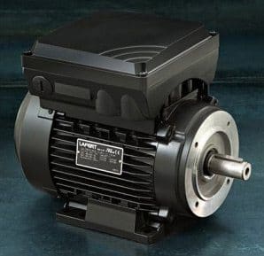
  4. If your energy costs average $0.03/kWh or more, and a motor is operated for at least 4,000 hour per year, an energy-efficient motor is a worthwhile investment. The higher purchase price will usually be repaid through energy savings within 2 years.

Here is a chart to help decide when to select an energy efficient motor:

Choose a new energy-efficient motor if:

Your energy costs are:Annual hours of use equals or exceeds:
$0.02/kWh6,000
$0.03/kWh4,000
$0.04/kWh3,000
$0.05/kWh2,000

Table 1 indicates how breakeven rewind costs vary with respect to motor operating hours and simple payback criteria. The breakeven cost is expressed as a percentage of a replacement energy-efficient motor price.

A new energy-efficient motor should be purchased if the rewind cost exceeds the stated breakeven point. Table 1 may be used for NEMA Design B motors in the 5- to 125-hp size range.

Assumptions used in the preparation of this table include an expected 2 percent loss in an average standard motor efficiency due to rewinding, replacement with an average energy-efficient motor operated at a 75 percent load factor, and a list price discount rate of 65 percent.

Table 1 - Breakeven Rewind Cost as a Percentage of an Energy-Efficient Motor Price

Simple Payback Criteria (Years)Annual Operating Hours
8,0006,0003,000
330%45%65%
25%65%70%

You can easily complete a cost-effectiveness analysis for a rewinding. If you can be assured that the past and prospective rewinds comply with all the foregoing recommended practices, the original efficiency could be maintained. Otherwise, two points should be subtracted from your standard motor efficiency to reflect expected rewind losses.

Annual energy and cost savings are determined by inputting the appropriate energy-efficient motor performance, operating hours, electricity price, and load factor into Equations below. The incremental cost of procuring the premium-efficiency unit is the quoted price for the new motor less the rewind price and any utility rebate.

Determining Annual Energy Savings
Where:

hp = Motor nameplate rating
L = Load factor or percentage of full operating load
Estd = Standard motor efficiency under actual load conditions
EHE = Energy-efficient motor efficiency under actual load conditions as

The simple payback for the energy-efficient motor is simply the incremental cost divided by the total annual energy conservation benefits.


Motor Rewind 10 hp (VIDEO)

Cant see this video? Click here to watch it on Youtube.

Reference: Energy-Efficient Electric Motor Selection Handbook – Gilbert A. McCoy, Todd Litman and John G. Douglass

Selection Of Crane Duty Motors (Part 1)

$
0
0
Selection Of Crane Duty Motors

Selection Of Crane Duty Motors (Photo By polyglot via Flickr)

Introduction

The operating conditions such as duty cycle, startup, temperature and operating environment are vital considerations in the motor efficiency and reliability. It is absolutely essential to match the motors to their specified operating conditions for minimizing stresses on the motors and to get predetermined performance and life.

One of the areas, in which significant technical requirements are considered lightly or even neglected, is selection of motors for operating various types of cranes and hoists.

These motors are specifically termed as “Crane Duty Motors” and are supplied by all the manufacturers.

Effort is made in this article to discuss in brief the vital factors required to be considered invariably when selecting the motor for performing the crane duty.


Definitions Of Technical Terms

Some technical terms used frequently in intermittent duty drives and hoisting are defined as follows:

1. Duty

Operation of the motor at the declared load(s) including starting, electric braking, no load and rest and de-energised periods to which the motor is subjected, including their durations and sequence in time.

2. Cyclic duration factor

The ratio of the period of energisation/loading, including starting and electric braking, to the duration of the one complete duty cycle expressed as percentage.

Cyclic duration factor

Generally the values for the CDF used are 25%, 40%, 60% and 100%.

3. Starting

The process of energizing a motor to bring it up to rated speed from rest.

4. Jogging or inching

This is an incomplete start during which the motor does not attain more than 25% of the rated speed.

5. Electric braking

A system in which a braking action is applied to an electric motor by causing it to act as a generator.
6. DC Injection braking

A form of braking of an induction motor in which a separate dc supply is used to magnetize the motor.

7. Plug braking

A form of electric braking of an induction motor obtained by reversing the phase sequence of its any two lines.


Duty Type and Class Of Rating

Before going to the principle discussion, it is necessary to throw some light on two of the most important technical requirements to be considered for better understanding.

Duty cycle assigned to the motor is one of the important factors in selection and operation of motors for several reasons, as it depends on how often and howlong a motor operates.

In accordance with Indian Standard IS:12824-1989; Types of Duty and Classes of Rating Assigned to Rotating Electrical Machines. The motors are to be designed for the standard duty cycles as given in Table.1 below.

Table.1 – Types of duty for electric motors

Duty TypeMotor performance requirements
S1Continuous running duty – The motor works at a constant load round the clock or runs for adequate time to reach thermal equilibrium.
S2Short-time duty – The motor works at a constant load for a definite time, but not long enough to reach thermal equilibrium. The rest periods are long enough for the motor to cool down to the ambient temperature.
S3Intermittent periodic duty – The motor works with a sequence of identical duty cycles comprising of period of running at a constant load and rest and de-energized period. Thermal equilibrium is never reached due to these periods being too short. Starting current has little effect on temperature rise.
S4Intermittent periodic duty with starting – The motor works with a sequence of identical duty cycles, each cycle consisting of significant periodof starting, a period of running at a constant load and rest and de-energized period. Thermal equilibrium is never reached due to these periods being too short, but starting current affects temperature rise.
S5Intermittent periodic duty with electric braking – The motor works with a sequence of identical duty cycles, each cycle consisting of a period of starting, a period of running at a constant load, a period of rapid electric braking and rest and de-energized period. Thermal equilibrium is never attained due to periods of operating, rest and de-energized state being too short
S6Continuous operation periodic duty – The motor works with a sequence of identical duty cycles, each cycle consisting of a period of running at a constant load and a period of running at no load without rest and de-energized period. Thermal equilibrium is never reached due to operation period at no load is too short.
S7Continuous operation periodic duty with electric braking – The motor works with a sequence of identical duty cycles, each cycle consisting of a period of starting, a period of running at a constant load and a period of electric braking. Thermal equilibrium is never reached, as rest and de-energized period is not there.
S8Continuous operation with periodic related variations in load and speed – The motor works with a sequence of identical duty cycles, each cycle consisting of a period of running at a constant load corresponding to a definite speed of rotation, followed by one or more periods of running at other constant loads at different speed.Thermal equilibrium is never reached, as rest and de-energized period is not there.
S9Duty with non-periodic load and speed variations – The motor works generally at a load and speed, which are varying non-periodically within permissible operating range including frequent application of overloads that may exceed the ratingof motor. Thermal equilibrium is never reached, as rest and de-energized period is not there.

Classes of rating assigned to the electric motors are as given in Table.2 below. It may be noted that while assigning classes of rating, the motors should invariably comply with the requirements of Indian Standard referred above.

Table.2 – Class of ratings for electric motors

Class of RatingPhilosophy for operation of motor
Maximum continuous ratingThe motor may be operated continuously for unlimited period at the load and service conditions assigned by the manufacturer.
Short time ratingStarting at ambient temperature, the motor may be operated continuously for limited period at the load and service conditions assigned by the manufacturer.
Equivalent continuous dutyThe motor may be operated at the load and service conditions assigned by the manufacturer for the test purposes until thermal equilibrium is attained. This is considered to be equivalent to one of the periodic duty defined in duty type S3 to S8 or to the duty type S9.
Periodic duty type ratingThe motor may be operated for duty cycles at the load and service conditions assigned by the manufacturer. When applied to the motor, this class of rating corresponds to the periodic duty S3 and S6 types maintaining time of duty cycle 10 minutes and one of the cyclic duration factors (CDF) with values – 15, 25, 40 or 60 percent.
Non-periodic duty type ratingThe motor may be operated non-periodically for dutycycles having varying loads over varying speed and service conditions, including overloads, assigned by the manufacturer. When applied to the motor, this class of rating corresponds to the non-periodic duty with non-periodic load and speed variations as per duty type S9.

Designation of Duty Types and Class of Ratings

The duty types and class of ratings designated to the motor should be indicated on the nameplate following the rated output as discussed hereunder.

1. If no designation is indicated following the rated output, then the motor should be considered suitable for maximum continuous rating, i.e. S1 duty.

2. For the duty type S2, the duration of duty should be indicated in minutes after S2. For example, “S2 60 minutes”.

3. For the duty type S3 and S6, indication of the cyclic duration factor (CDF) in percentage should follow S3 or S6. For example, “S3 15 %” or “S6 60%”.

4. For the duty type S4 and S5, the indication of S4 and S5 should be followed by indication of the CDF in percentage, the moment inertia of motor (JM) and the moment of inertia of load (Jext), both referred to the motor shaft. For example, S4 25 %, JM= 0.15 km-m2, Jext= 0.7 km-m2.

5. For the duty type S7, the indication of S7 should be followed by indication of the moment inertia of motor (JM) and the moment of inertia of load (Jext), both referred to the motor shaft. For example, S7, JM= 0.15 km-m2, Jext= 0.7 km-m2.

6. For the duty type S8, the indication of S8 should be followed by indication of the moment of inertian of the motor (JM) and the moment of inertia of the load (Jext), both referred to the motor shaft,together with tee load, speed and cyclic duration factor for each speed condition.

For example:

S8 JM = 0.4 kg-m2, Jext = 4 kg-m2

  • 16 kW, 740 rpm 30 percent
  • 40 kW, 1460 rpm 30 percent
  • 25 kW, 980 rpm 40 percent


Need of specifying Duty Type and Class of Rating

For the majority of applications, the motors assigned with duty types S1, S2, S3, and S6 would be found appropriate respectively for continuous rating, short time rating, intermittent ratings or continuous rating with intermittent loading.

However for special duties, such as cranes, the motors with equivalent continuous rating, short time rating or intermittent rating would be required.

In order to get the motor that meets the requirements for special duties, it is essential that the vendor is furnished all the data of required duty by the purchaser.

In case the data is insufficient, there should be an agreement by discussion between the purchaser and the vendor for the type of motor. If the duty type and class or rating are not specified or incorrect values are specified, the vendor may arrive at the motor rating and select a suitable motor to met the require duty from his standard list of ratings and the purchaser may not get the correct motor and cause problems during actual service.

Moreover, when a motor is designed for cyclic duty for crane, it should also be possible to subject the said motor for testing for equivalent continuous, short time or intermittent rating such that the motor would satisfactorily meet the actual duty requirements whilst complying with the specified conditions.

Will be continued in 2 days…

References:
  1. Efficient Electric Motor Systems Handbook, by Todd Litmann
  2. IS:12824-1989; Types of Duty and Classes of Rating Assigned to Rotating Electrical Machines
  3. The Technical Literature of Indian Motor Manufacturers

Selection Of Crane Duty Motors (Part 2)

$
0
0
Selection Of Crane Duty Motors (Part 2)

Selection Of Crane Duty Motors (on photo: Electric wire rope hoist for LNG (liquified natural gas) - STAHL CraneSystems GmbH by DirectIndustry)


Continued from first part: Selection Of Crane Duty Motors (Part 1)


Crane Duty Motors

Types of Crane Duty Motors

Following two types of motors are widely used for crane duty applications.

The crane motors are duty type rated for developing high starting torque with low starting current. The motors are designed to withstand stresses due to frequent starts/stops and reversals. Also, a rapid acceleration is achieved by high pull out torque/rotor inertia ratio.

Generally, the motors assigned duty type S3, S4 and S5 are considered for crane applications.

The crane duty motors are specially designed to offer satisfactory performance and long lives for service on the cranes and hoists.

These motors may also be used for similar applications such as material handling, sluice operation on dams/weirs, lifts of all types and in rolling mills as auxiliary motors or wherever operating drives are required for intermittent services.


Applicable Standards

The crane duty motors should generally comply with Indian Standards provided in Table.3 below:

Table.1 Standards applicable to motors

Indian StandardTitleApplicability
IS:1231-1974Dimension of Three Phase Foot Mounted Induction MotorsFor dimensions of motor
IS :2223-1983Dimension of Flange Mounted AC Induction MotorsFor dimensions motor
IS:325-1996Three Phase Induction Motors – SpecificationFor specification and performance of motor
IS:1271-985Specification for Thermal Evaluation and Classification of Electrical InsulationFor insulation of stator and rotor windings
IS:12824-1989Types of Duty and Classes of Rating Assigned to rotating Electrical MachinesFor duty class and assigned rating for motors
IS:4691-1985Degrees of Protection Provided by Enclosures for Rotating Electric MachinesFor protection to enclosures
IS:6362-1995Designation of Methods of Cooling for Rotating Electrical MachinesFor cooling of motors
IS:2253-1974Designations for Types of Construction and Mounting Arrangements of Rotating Electrical MachinesFor type of mounting and frame size
IS:12065-1987Permissible Limits of Noise Levels for Rotating Electrical MachinesFor noise level
IS:12075-1987Mechanical Vibration of Rotating Electrical Machines with Shaft Heights 56 mm and Higher – Measurement, Evaluation and Limits of Vibrations SeverityFor vibration level
IS:4029-1967Guide for Testing of Three Phase Induction MotorsFor testing of motors
IS :3177–1977Code of Practice for Electric overhead Travelling Cranes and Gantry Cranes other than Steelworks CranesFor understanding requirements of cranes

Standard operating conditions

In accordance with the provisions made in the applicable Indian Standard, the motors should be able to perform satisfactorily for the power supply parameters, site conditions and insulation class as provided in Table.2, unless specific parameters are furnished.

Table.2 – Power supply parameters, site conditions and insulation class for AC motors

Supply voltage with permissible variation415 volts ±10%, 3 phase
Supply frequency with permissible variation50 Hz + 5%
Combined voltage and frequency variation±10% (absolute sum)
UnbalanceStandard motors capable to operate under unbalance supply conditions, wherein negative and zero sequence voltage components not to exceed individually 2% of positive phase sequence component
Ambient temperature-10°C to 40°C
AltitudeUp to 1000 m
HumidityUp to 100%
InsulationClass “F” in Squirrel cage motors
Class “F/F” for both stator and rotor in slip ring motors

Ambient temperature

The rated output of motor specified by the vendor is generally at 40°C ambient temperature. For temperatures other than 40°C, a duration factor should be applied as indicated Table.3.

Table.2 – Ambient temperature and deration factors for AC motors

Ambient temperatureDeration factor
45°C0.95
50°C0.88
55°C0.83
60°C0.75

Salient technical and constructional features of crane duty motors

The technical and constructional features of crane duty motors as follows are more or less similar to that are found in the standard continuous duty motors.

  • Material and construction of stator frame and end shields
  • Material and construction of stator and rotor cores
  • Bearings at non-drive and drive ends
  • Material of construction of shaft
  • Earthing to stator frame and terminal box
  • Mounting of motor – foot mounted or flange mounted
  • Material, construction and position of terminal box
Specific technical and constructional features required to be incorporated in the specification for the crane duty motors are listed hereunder so that the motors provide desired trouble free, predetermined and optimum performance.

The motor rating should be decided based on its thermal capability taking into consideration few or all factors listed hereunder as per duty requirements.

    1. Optimised nos. of starts and frequency of starts for all the motors should be specified for the design purpose (Starting class);
    2. Percentage of time during each operating cycle the motor is energised, i.e. Cyclic duty factor (CDF);
    3. The intermittent duty type S3, S4 or S5 should be defined correctly based on exact operational requirements of cranes. The number and type of cycle per hour should be (Duty class) should be considered;

    It is vital to specify the correctly calculated “Cyclic Duty Factor” (CDF) for crane duty motors. Calculations for deriving CDF for type duty S3, S4 and S5 are given in succeeding paragraphs for reference.

    The motors should have higher than normal pullout torques. As the motors are supposed to experience large no. of starts, it is necessary that the accelerating time of the system should be as small as possible. The higher pull out torque ensures rapid acceleration irrespective of drop in effective torque due to stepped rotor resistance.

    Moreover for minimizing acceleration time, total inertia of the system, comprising of moment of inertia of motor plus moment of inertia of load, should be minimum. This can be achieved by keeping lower than normal rotor inertia in comparison to standard continuous duty motors.

    The torque available from the motor varies as the square of the motor terminal voltage, an allowance for voltage drop in long cables, live rails and collectors must be considered. The voltage drop is significant when the motor is operated at pull out torque point, since current at this point is much higher than the rated current.

    The motors should be able to withstand 1.5 times the rated current for 2 minutes without suffering damage. This feature makes the motor suitable for intermittent and severe duties experienced on the crane or similar applications.

    All 4, 6, 8, and 10 pole motors should be designed for withstanding an overspeed of 2.5 times rated synchronous speed or minimum 2000 rpm, whichever is less.

    The squirrel cage motors should be provided single cylindrical shaft extension and the wound rotor (slip ring) motors should be provided double cylindrical shaft extension.

    The stator and rotor windings should be impregnated with Class ‘F’ thermosetting varnish insulation. In stringent cases, Class ‘H’ insulation may also be considered.

    Additionally, the rotor windings should be braced with resin-glass banding to give protection against centrifugal forces experienced by overhang during overspeed and frequent reversals. Gel-coat may be painted on the winding overhang for better consolidation and protection from vibration.

    Size of the terminal box should be adequate for to facilitate splitting of power cables cores and terminate comfortably. In slip ring motors, the cables for main power supply and from slip rings are usually accommodated in the same terminal box for simplifying wiring and maintenance.

    Hence in case of slip ring as well as squirrel cage motors, if required, the cable box size may be increased by providing an attachment of cable splitter box (generally of trapezoidal shape) to the main terminal box.

    The rotors of squirrel cage and wound rotor motors should be dynamically balanced to ensure lowest possible vibration.

    It should be preferred to use the metallic cooling fans in the wound rotor motors. PVC or plastic fans are likely to be deformed due to high temperature in housing due to slip rings and get damaged.

    As the motor would generate more heat due to intermittent switching operations, the painting should be heat resistant, specifically able to withstand higher temperatures.

    The standard crane duty motors should be provided IP55 Degree of protection as per IS:4691. The cooling code of motor should be IC411 as per IS:6362.

    The insulation resistance of the slip-ring unit should be high enough ensuring minimum wear and breakdown. The brush holders, made as a complete unit, should be easily replaceable. The slip-ring should be large enough to encounter starting currents and for proper installation of brushes in slip ring motors.

    The enclosure for slip-rings should be dustproof and easily accessible for inspection.

    For higher rated would rotor motors, separate disc should be provide between the slip-ring and rotor windings to prevent ingress of carbon dust from brushes into windings.

    Will be continued in 2 days…

    References:
    1. Efficient Electric Motor Systems Handbook, by Todd Litmann
    2. IS:12824-1989; Types of Duty and Classes of Rating Assigned to Rotating Electrical Machines
    3. The Technical Literature of Indian Motor Manufacturers
    Viewing all 139 articles
    Browse latest View live