Quantcast
Channel: Electric Motor - Technical Articles | EEP - Electrical Engineering Portal
Viewing all 139 articles
Browse latest View live

Selection Of Crane Duty Motors (Part 3)

$
0
0
Selection Of Crane Duty Motors

Selection Of Crane Duty Motors (On photo: Single girder overhead traveling crane - max. 12.5t, 4-30m of Demag Cranes & Components via DirectIndustry.com)


Continued from second part: Selection Of Crane Duty Motors (Part 2)


Derivation Of Cyclic Duration Factor From Different Duty Cycles

S3 – Intermittent Periodic Duty
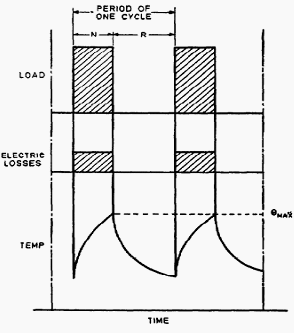
Intermittent Periodic Duty

S3 - Intermittent Periodic Duty


N = Duration of motor operation under rated conditions
R = Duration of motor at rest and de-energised
ØMax = Maximum temperature attained during Duty cycle

CDF formula for S3

Unless otherwise specified, the duration of the duty cycle is 10 minutes. The recommended values for CDF are 25, 40 and 60 percent.


S4 – Intermittent Periodic Duty with starting
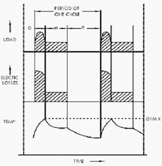
S4 - Intermittent Periodic Duty with starting

S4 - Intermittent Periodic Duty with starting


D = Duration of starting
N = Duration of motor operation under rated conditions
R = Duration of motor at rest and de-energised
ØMax = Maximum temperature attained during Duty cycle

CDF formula for S4


S5 – Intermittent Periodic Duty with starting and breaking
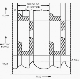
S5 – Intermittent Periodic Duty with starting and breaking

S5 – Intermittent Periodic Duty with starting and breaking

D = Duration of starting
N = Duration of motor operation under ratedconditions
R = Duration of motor at rest and de-energised
F = Duration for electric braking
ØMax = Maximum temperature attained during Duty Cycle


Starting Of Crane Duty Motors

The squirrel cage motors are started with direct-on-line starters in most of the cranes. Few cranes, operated more or less on continuous basis, are found operated through a variable voltage variable frequency (VVVF) drive.

For intermittent duty cranes, provision of VVVF would be costly affair.

The slip-ring or wound rotor motors are usually started by means of variable resistance in the rotor circuit to get required starting torque at reduced starting current. The value of external starting resistance can be calculated as under.

External starting resistance formulae

K = Constant depends on line voltage drop; varies from 0.6 to 1.0. Generally a value 0.8 can be considered.
VR = Rotor voltage (Volts)
IR = Rotor Current
TFL = Full load torque (kg-m)
TLR = Locked Rotor (Starting) Torque
Rrt = Rotor resistance in Ohms per phase
Rext = External rotor resistance per phase to be added (Ohms) to get torque TLR at stand still.

Rrt is generally small compared to Rext and may be neglected. However, if required, approximate Rrt can be calculated by following relation:

Rotor resistance in Ohms per phase

The starting torque can be increased up to the value of maximum torque available for that particular design. Usually, it is possible to obtain the starting torque as high as 2.5 times the normal torque.


Selection Of Motors

Choice of cage and wound motors may be based on the following criteria.

Squirrel Cage Motors may be used for various applications as follows:

  • The driven equipment is to be accelerated rapidly with a fixed sequence of operation and uniform load conditions, e.g. mechanical workshop crane.
  • If the load conditions are almost identical for both directions of rotation, e.g. long travel or cross travel of gantry crane.
  • In the cranes, which are running at single speed without speed control.
  • If site conditions are dusty, corrosive, these motors with totally enclosed fan cooled construction would be robust and would provide services with least maintenance.
  • Where the cost factor is to be considered, as cost of cage motor is less than that of slip-ring motor;
  • The squirrel cage motors for crane duty are available normally up to 250M frame size.

Slip-ring motors may be used for various applications as follows:

  • Where very precise speed control is required for the crane, e.g. inching, slow and fast handling of load during hoisting and lowering, alignment of crane over a furnace opening, etc.
  • In case of non-uniform loading conditions and operation is to be carried out in nos. of sequences.
  • The cranes are required to perform large number of starting and reversals during operation.
  • The cranes are required starting torque of more than 2.5 times the rated torque in general.

Selection

The crane duty motors are always supposed to operate under varying load conditions and sequential switching due to requirement of handling materials of varied weights (i.e. loads).

Many continuous duty motors even operate under varying load conditions due to chemical process requirements.

As a common practice, where such variable loads are to be operated, a motor rating is selected based on the highest anticipated load. However, more efficient and cost effective approach is to select the motor with optimum rating on the basis of the load duration curve for the particular application.

Selection made on this basis also provides equally effective and satisfactory operation.

Thus as an alternative, it is better to select the motor having rating slightly lower than the peak anticipated load and let it be operated at overload for a short time duration, rather than selecting the motor of high rating that would operate at full capacity for only a short period providing optimum efficiency only for that much duration. Only concern for motors operating at higher than its rating is the thermal capacity of motor, which determines the speed of degradation of the winding insulation.

Applications of various factors discussed in foregoing paragraphs combined with this suggestion would provide better result. However, accurate rating is very difficult to determine for crane duty applications.

CONCLUSION

Most vital and primary technical consideration for selection of the motor for any particular application is the torque required by the load during starting and acceleration periods, especially the relationship between the maximum torque or breakdown torque generated by the motor and the start-up torque or locked rotor torque for both periods.

The thermal capability of motor is determined based on the duty / load cycle. Additionally, where the totally enclosed fan cooled (TEFC) motor is operated with speed variations, the cooling may be insufficient when the motor is operated at speeds below its rated value.

If the ambient temperature is more than 40°C, derating factor would affect the selection of motor. Good estimate of the switching frequency can help in selecting the appropriate motor for the proposed duty cycle.

Reliability is of prime importance in all the services, however, it is general practice to grossly oversize the motor unnecessarily for better reliability, which results into sub-optimal energy performance. Better understanding of the power system and knowledge of operating parameters can certainly aid in reducing over sizing with no adverse effect on reliability.


References:
  1. Efficient Electric Motor Systems Handbook, by Todd Litmann
  2. IS:12824-1989; Types of Duty and Classes of Rating Assigned to Rotating Electrical Machines
  3. The Technical Literature of Indian Motor Manufacturers

NEMA Definition Of Motor Full Load Nominal Efficency (Standard MG1-12.54.2)

$
0
0
NEMA Definition Of Motor Full Load Nominal Efficency (Standard MG1-12.54.2)

NEMA Definition Of Motor Full Load Nominal Efficency (Standard MG1-12.54.2) - On photo SIEMENS's new Simogear geared motors

NEMA standard MG1-12.54.2

Efficiency is defined as the ratio of the power output divided by the power input. Machine losses are in the form of heat, and include:

  1. Stator winding loss,
  2. Rotor loss,
  3. Core loss (hysteresis and eddy current),
  4. Friction and windage, and
  5. Stray load loss.

NEMA standard MG1-12.54.2 provides instructions for establishing the value of efficiency.

The standard states that the nominal efficiency shown on the motor nameplate shall not be greater than the average efficiency of a large population of motors of the same design.

Also, the full load efficiency, when operating at rated voltage and frequency, will not be less than the minimum value associated with the nominal value. Care should be taken in comparing efficiencies from one motor manufacturer to another. It is difficult to compare efficiencies based on published, quoted or test data, due to the fact that there is no single standard method which is used throughout the industry.

The most common referred to standards are IEEE 112 (U.S.), IEC (International), JEC-27 (Japanese), BS-269 (British) and ANSI C50.20 (same as IEEE 112).

IEEE 112 is used more than any of the others in the United States, while allowing for a variety of test methods to be used. The preferred procedure is IEEE method B, where the motor is operated at full load, and the power is directly measured.

Generally, larger motors will be more efficient than smaller motors.

Today’s premium efficiency 3-phase motors have efficiencies ranging from 86.5% at 1 hp to 95.8% at 300 hp. The efficiency value that appears on the nameplate is the “nominal full-load efficiency” as determined using a very accurate dynamometer and a procedure described by IEEE Standard 112, Method B.

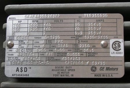
GE  motor 250H 4P 460V TEBC nameplate

GE motor 250H 4P 460V TEBC nameplate


The nominal value is what the average would be if a substantial number of identical motors were tested and the averages of the batch were determined. Some motors might have a higher value and others might be lower, but the average of all units tested is shown as the nominal nameplate value. Thus, essentially the rating Nom Eff.

92.1 means this is an average efficiency of this motor model, but actual efficiency may vary. The efficiency is reduced by any form of heat, including friction, stator winding loss, rotor loss, core loss (hysteresis and eddy current), etc.

The actual motor efficiency is guaranteed to be within a band of this nominal efficiency by the manufacturer. The efficiency band varies from manufacturer to manufacturer.

The maximum allowable “band” is 20% set by NEMA.

This is a large range; therefore pay close attention to the manufacturer’s actual minimum guarantee!

Reference: Understanding Motor Nameplate Information: NEMA vs. IEC Standards – Continuing Education and Development, Inc.

Motor Service Factor (SF) Defined By NEMA

$
0
0
Motor Service Factor (SF) Defined By NEMA

Motor Service Factor (SF) Defined By NEMA

Permissible horsepower loading

Motor Service Factor (SF) is the percentage of overloading the motor can handle for short periods when operating normally within the correct voltage tolerances. This is practical as it gives you some ‘fudge‘ in estimating horsepower needs and actual running horsepower requirements.

It also allows for cooler winding temperatures at rated load, protects against intermittent heat rises, and helps to offset low or unbalanced line voltages.

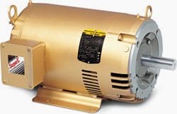
BALDOR Open Drip Proof C-Face Foot Mounted motor - 1/3Hp-100Hp NEMA 56C-404TC

BALDOR Open Drip Proof C-Face Foot Mounted motor - 1/3Hp-100Hp NEMA 56C-404TC


For example, the standard SF for open drip-proof (ODP) motors is 1.15. This means that a 10-hp motor with a 1.15 SF could provide 11.5 hp when required for short-term use. Some fractional horsepower motors have higher service factors, such as 1.25, 1.35, and even 1.50.

NEMA defines service factor as a multiplier, when applied to the rated horsepower, indicates a permissible horsepower loading, which may be carried under the conditions specified for the service factor at rated voltage and frequency.

This service factor can be used for the following:

  1. To accommodate inaccuracy in predicting intermittent system horsepower needs.
  2. To lengthen insulation life by lowering the winding temperature at rated load.
  3. To handle intermittent or occasional overloads.
  4. To allow occasionally for ambient above 40°C.
  5. To compensate for low or unbalanced supply voltages.

NEMA does add some cautions, however, when discussing the service factor:

  1. Operation at service factor load for extended periods will usually reduce the motor speed, life and efficiency.
  2. Motors may not provide adequate starting and pull-out torques, and incorrect starter/overload sizing is possible. This in turn affects the overall life span of the motor.
  3. Do not rely on the service factor capability to carry the load on a continuous basis.
  4. The service factor was established for operation at rated voltage, frequency, ambient and sea level conditions.

Most motors have a duty factor of 1.15 for open motors and 1.0 for totally closed motors.

Traditionally, totally enclosed fan cooled (TEFC) motors had an SF of 1.0, but most manufacturers now offer TEFC motors with service factors of 1.15, the same as on ODP motors. Most hazardous location motors are made with an SF of 1.0, but some specialized units are available for Class I applications with a service factor of 1.15.
The service factor is required to appear on the nameplate only if it is higher than 1.0.

Reference: Understanding Motor Nameplate Information: NEMA vs. IEC Standards – Continuing Education and Development, Inc.

7 Most Common Motor Enclosure Types Defined By NEMA Standards

$
0
0
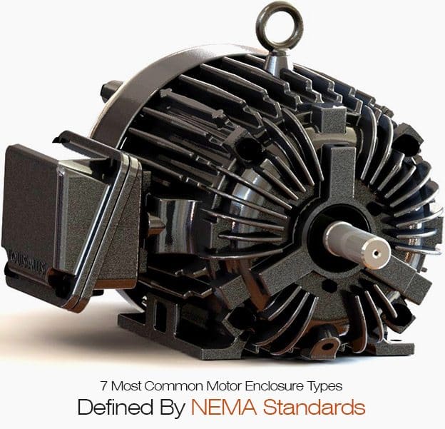
7 Most Common Motor Enclosure Types Defined By NEMA Standards

7 Most Common Motor Enclosure Types Defined By NEMA Standards (on photo: Louis Allis Pacemaker Premium NEMA motor - louisallis.com)

Important role of enclosure

The enclosure of the motor must protect the windings, bearings, and other mechanical parts from moisture, chemicals, mechanical damage and abrasion from grit.

NEMA standards MG1-1.25 through 1.27 define more than 20 types of enclosures under the categories of open machines, totally enclosed machines, and machines with encapsulated or sealed windings.

The 7 most common types of enclosures are:

1. Open Drip Proof (ODP)

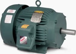
Premium Efficient Super-E motor with Open Drip Proof (ODP) construction by BALDOR

Premium Efficient Super-E motor with Open Drip Proof (ODP) construction by BALDOR


Allows air to circulate through the windings for cooling, but prevent drops of liquid from falling into motor within a 15 degree angle from vertical. Typically used for indoor applications in relatively clean, dry locations.


2. Totally Enclosed Fan Cooled (TEFC)

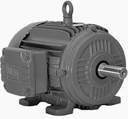
Weg NEMA Premium Efficiency - Three Phase TEFC Motors

Weg NEMA Premium Efficiency - Three Phase TEFC Motors


Prevents the free exchange of air between the inside and outside of the frame, but does not make the frame completely air tight. A fan is attached to the shaft and pushes air over the frame during its operation to help in the cooling process.

The ribbed frame is designed to increase the surface area for cooling purposes.

The TEFC style enclosure is the most versatile of all. It is used on pumps, fans, compressors, general industrial belt drive and direct connected equipment.

Total Enclosed Fan Cooled vs Open Drip Proof (TEFC vs ODP)

Cant see this video? Click here to watch it on Youtube.


3. Totally Enclosed Non-Ventilated (TENV)

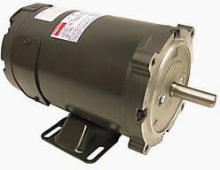
DAYTON DC Motor, PM, TENV, 1/3 HP, 1800 rpm, 24VDC

DAYTON DC Motor, PM, TENV, 1/3 HP, 1800 rpm, 24VDC


Similar to a TEFC, but has no cooling fan and relies on convention for cooling. No vent openings, tightly enclosed to prevent the free exchange of air, but not airtight.

These are suitable for uses which are exposed to dirt or dampness, but not very moist or hazardous (explosive) locations.

4. Totally Enclosed Air Over (TEAO)

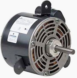
US Motors - Refrigeration Duty TEAO Motor, 1/2 HP, 3-Phase, 1140 RPM Motor

US Motors - Refrigeration Duty TEAO Motor, 1/2 HP, 3-Phase, 1140 RPM Motor


Dust-tight fan and blower duty motors designed for shaft mounted fans or belt driven fans. The motor must be mounted within the airflow of the fan.


5. Totally Enclosed Wash down (TEWD)

Baldor's Washdown Duty Motor

Baldor's Washdown Duty Motor for food processing, packaging, pharmaceuticals, or applications where motors are regularly exposed to high pressure wash down.


Designed to withstand high pressure wash-downs or other high humidity or wet environments. Available on TEAO, TEFC and ENV enclosures totally enclosed, hostile and severe environment motors:

Designed for use in extremely moist or chemical environments, but not for hazardous locations.

6. Explosion-proof enclosures (EXPL)

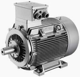
SIEMENS's explosion proof motor for hazardous environments

SIEMENS's explosion proof motor for hazardous environments, such as in chemical plants, the oil industry, in gas works, in wood and plastic processing industry or in agriculture.


The explosion proof motor is a totally enclosed machine and is designed to withstand an explosion of specified gas or vapor inside the motor casing and prevent the ignition outside the motor by sparks, flashing or explosion.

These motors are designed for specific hazardous purposes, such as atmospheres containing gases or hazardous dusts. For safe operation, the maximum motor operating temperature must be below the ignition temperature of surrounding gases or vapors.

Explosion proof motors are designed, manufactured and tested under the rigid requirements of the Underwriters Laboratories.


7. Hazardous Location (HAZ)

Motor 3-Phase, 5 HP - to Power Fans, Blowers, Pumps or Air Compressors in Areas That Meet the National Electrical Code for Hazardous Locations

Motor 3-Phase, 5 HP - to Power Fans, Blowers, Pumps or Air Compressors in Areas That Meet the National Electrical Code for Hazardous Locations


Hazardous location motor applications are classified by the type of hazardous environment present, the characteristics of the specific material creating the hazard, the probability of exposure to the environment, and the maximum temperature level that is considered safe for the substance creating the hazard.

The format used to define this information is a class, group, division and temperature code structure as defined by the National Electric Code (NFPA-70).

The following hazardous locations are defined:

1) CLASS I

  • Group A: Acetylene
  • Group B: Butadiene, ethylene oxide, hydrogen, propylene oxide, manufactured gases containing more than 30ydrogen by volume.
  • Group C: Acetaldehyde, cyclopropane, diethyl ether, ethylene.
  • Group D: Acetone, acrylonitrile, ammonia, benzene, butane, ethanol, ethylene dichloride, gasoline, hexane, isoprene, methane (natural gas), methanol, naphtha, propane, propylene, styrene, toluene, vinyl acetate, vinyl chloride, xylene.

2) CLASS II

  • Group E: Aluminum, magnesium, and other metal dusts withsimilar characteristics.
  • Group F: Carbon black, coke or coaldust.
  • Group G: Flour, starch orgrain dust.

3) CLASS III

  • Easily ignitable fibers,such asrayon, cotton, sisal, hemp, cocoa fiber, oakum, excelsior and other materials of similar nature.
The NEMA enclosure description is similar to the IEC Index of Protection (IP) code. The NEMA designations are more descriptive and general, whereas the IEC IP codes are more precise and narrowly defined by a 2-digit code, with the first digit defining how well protected the motor is from solid objects and the second digit describing how well protected the motor is from moisture.

For example, a NEMA “OpenDrip Proof (ODP)” motor corresponds to an IP22 and a NEMA “Totally Enclosed” motor corresponds to an IP54, a NEMA “WeatherProof” motor to an IP45, and a NEMA “Wash-Down” motor toan IP55.

Reference: Understanding Motor Nameplate Information: NEMA vs. IEC Standards – Continuing Education and Development, Inc.

Drive Design in Electric Vehicles

$
0
0
Drive Design in Electric Vehicles

Drive Design in Electric Vehicles (on photo by cnet.com.au: Renault Fluence Z.E. presented at the 2011 Melbourne Motor Show)

Introduction

Good Evening all, in this session I’m going to present some of the issues in drive design in the field of Electric Vehicle.

I’ve organized the whole series into modules so that each module can be covered with:

  • Drive Design issues
  • Comparison of different drives for EV applications
  • Electrical Machine design – Viewpoints
  • Science of Machines
  • Design of Induction Machines
  • Design of BLDC Machines
  • Design of SRM Machines
  • Optimization
  • Recent trends in design

Let’s start the session with a comprehensive introduction about drives used in Industry as well EV applications…


EV drives versus Industrial drives

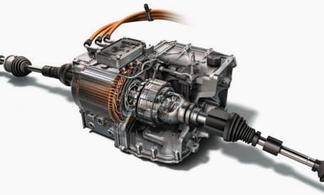
GM's new electric drive module

GM's new electric drive module in the 2014 Spark EV features a GM-designed-and-manufactured 120-kW permanent magnet traction motor (visible on the left side) and smart use of key carryover components from Volt and the two-mode hybrid transmission.


In EVs, only traction motor delivers torque to the driven wheels. Thus the vehicle performance is completely determined by the torque speed or powerspeed characteristic of the traction motor.

A vehicle, in order to meet its operational requirement, such as the initial acceleration and grade ability with minimum power mentioned above, operation entirely in constant power is needed. Operation entirely in constant power is, however, not possible for any practical vehicle.

It can be observed that the EV motor drive is expected to be capable of offering a high torque at low speed for starting and acceleration, and a high power at high speed for cruising.

At the same time, the speed range under constant power is desired as wide as possible. Ideally, eliminating the constant torque region would provide the minimum power rating of the motor, but this is not physically realizable.

Desired output characteristicsc of electric motor drives in EVs

Desired output characteristicsc of electric motor drives in EVs


Under the normal mode of operation, a typical electric motor drive designed for industrial applications can provide constant rated torque up to its base or rated speed. At this speed, the motor reaches its rated power limit. The operation beyond the base speed up to the maximum speed is limited to this constant power region.

The range of the constant power operation depends primarily on the particular motor type and its control strategy.

The maximum available torque in the natural mode of operation decreases inversely with the square of the speed. Although the machine torque in the natural mode decreases inversely with the square of the speed, for some extremely high speed motors the natural mode of operation is an appreciable part of its total power-speed profile.

Inclusion of this natural mode for such motor drives may result in a reduction of the total power requirement.

Typical performances of an electric motor drives in industrial application

Typical performances of an electric motor drives in industrial application


Conclusions

Conclusions drawn from the above comparisons are :

  1. The power requirement (rated power) for acceleration performance (acceleration time and acceleration distance) decreases as constant power region ratio increases.
  2. Conversely, the torque requirement (rated torque) for acceleration increases as constant power region ratio increases. This results in a larger motor size and volume.
  3. Passing performance (passing time and passing distance) suffers considerably as the constant power region ratio increases.
  4. A motor’s maximum speed has a pronounced effect on the required torque of the motor. Low speed motors with the extended constant power speed range have a much higher rated shaft torque. Consequently, they need more iron and copper to support this higher flux and torque.
  5. As motor power decreases (due to extending the range of constant power operation), the required torque is increasing. Therefore, although the converter power requirement (hence the converter cost) will decrease when increasing the constant power range, the motor size, volume, and cost will increase.
  6. Increasing the maximum speed of the motor can reduce the motor size by allowing gearing to increase shaft torque. However, the motor maximum speed cannot be increased indefinitely without incurring more cost and transmission requirements.


Requirements of EVs on Electric Motor Drives

  • High instant power and high power density.
  • High torque at low speeds for starting and climbing, as well as high power at high speed for cruising.
  • Very wide speed range including constant-torque and constant-power regions.
  • Fast torque response.
  • High efficiency over wide speed and torque ranges.
  • High efficiency for regenerative braking.
  • High reliability and robustness for various vehicle-operating conditions.
  • Downsizing, weight reduction, and lower moment of inertia.
  • Fault tolerance
  • Reasonable cost
  • Suppression of electromagnetic interface (EMI) of motor controllers

Major Considerations in design

  1. The Type of frame structure
  2. Ventilation
  3. The bearing and shaft
  4. The Magnetic core dimensions & the winding

Design details required:

  1. The main dimensions of the stator.
  2. Details of stator windings.
  3. Design details of rotor and its windings
  4. Performance characteristics.

Specifications:

    • Number of phases
    • Frequency
    • Rated output in kW
    • Type of duty
    • Voltage connections
    • Temperature rise
    • Speed
    • Pullout torque
    • Starting torque
    • Starting current
    • Power factor
    • Efficiency/losses
    • Class of insulation

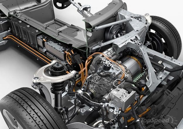
Motor drive mechanism of coming BMW i8 in 2015

Motor drive mechanism of coming BMW i8 in 2015 (photo by topspeed.com)


References:
  1. Electrical Machine Design – A.K.Sawhney
  2. Selection of Electric Motor Drives for Electric Vehicles – X. D. Xue, K. W. E. Cheng and N. C. Cheung
  3. Inputs from Google and Wikipedia

Sizing The DOL Motor Starter Parts (Contactor, Fuse, Circuit Breaker and Thermal Overload Relay)

$
0
0
Sizing The DOL Motor Starter Parts (Contactor, Fuse, Circuit Breaker and Thermal Overload Relay)

Sizing The DOL Motor Starter Parts (Contactor, Fuse, Circuit Breaker and Thermal Overload Relay)


Calculate size of each part of DOL motor starter for the system voltage 415V, 5HP three phase house hold application induction motor, code A, motor efficiency 80%, motor RPM 750, power factor 0.8 and overload relay of starter is put before motor.


Basic Calculation of Motor Torque and Current

  • Motor Rated Torque (Full Load Torque) = 5252xHPxRPM
  • Motor Rated Torque (Full Load Torque) = 5252x5x750 = 35 lb-ft.
  • Motor Rated Torque (Full Load Torque) = 9500xKWxRPM
  • Motor Rated Torque (Full Load Torque) = 9500x(5×0.746)x750 = 47 Nm
  • If Motor Capacity is less than 30 KW than Motor Starting Torque is 3xMotor Full Load Current or 2X Motor Full Load Current.
  • Motor Starting Torque = 3xMotor Full Load Current.
  • Motor Starting Torque = 3×47 = 142Nm.
  • Motor Lock Rotor Current = 1000xHPx figure from below Chart/1.732×415

Locked Rotor Current

CodeMin.Max.
A13.14
B3.153.54
C3.553.99
D44.49
E4.54.99
F52.59
G2.66.29
H6.37.09
I7.17.99
K88.99
L99.99
M1011.19
N11.212.49
P12.513.99
R1415.99
S1617.99
T1819.99
U2022.39
V22.4
  • As per above chart Minimum Locked Rotor Current  = 1000x5x1/1.732×415 = 7 Amp
  • Maximum Locked Rotor Current = 1000x5x3.14/1.732×415 = 22 Amp.
  • Motor Full Load Current (Line) = KWx1000/1.732×415
  • Motor Full Load Current (Line) = (5×0.746)x1000/1.732×415 = 6 Amp.
  • Motor Full Load Current (Phase) = Motor Full Load Current (Line)/1.732
  • Motor Full Load Current (Phase) = 6/1.732 =4Amp
  • Motor Starting Current = 6 to 7xFull Load Current.
  • Motor Starting Current (Line) = 7×6 = 45 Amp

1. Size of Fuse

Fuse as per NEC 430-52

Type of MotorTime Delay FuseNon-Time Delay Fuse
Single Phase300%175%
3 Phase300%175%
Synchronous300%175%
Wound Rotor150%150%
Direct Current150%150%
  • Maximum Size of Time Delay Fuse = 300% x Full Load Line Current.
  • Maximum Size of Time Delay Fuse = 300%x6 = 19 Amp.
  • Maximum Size of Non Time Delay Fuse = 1.75% x Full Load Line Current.
  • Maximum Size of Non Time Delay Fuse = 1.75%6 = 11 Amp.

2. Size of Circuit Breaker

Circuit Breaker as per NEC 430-52

Type of MotorInstantaneous TripInverse Time
Single Phase800%250%
3 Phase800%250%
Synchronous800%250%
Wound Rotor800%150%
Direct Current200%150%
  • Maximum Size of Instantaneous Trip Circuit Breaker = 800% x Full Load Line Current.
  • Maximum Size of Instantaneous Trip Circuit Breaker = 800%x6 = 52 Amp.
  • Maximum Size of Inverse Trip Circuit Breaker = 250% x Full Load Line Current.
  • Maximum Size of Inverse Trip Circuit Breaker = 250%x6 = 16 Amp.

3. Thermal Overload Relay

Thermal Overload Relay (Phase):

  • Min. Thermal Overload  Relay setting = 70%x Full Load Current(Phase)
  • Min. Thermal Overload Relay setting = 70%x4 = 3 Amp
  • Max. Thermal Overload  Relay setting = 120%x Full Load Current(Phase)
  • Max. Thermal Overload Relay setting = 120%x4 = 4 Amp

Thermal Overload Relay (Phase):

  • Thermal Overload Relay setting = 100% x Full Load Current (Line).
  • Thermal Overload Relay setting = 100%x6 = 6 Amp

4. Size and Type of Contactor

ApplicationContactorMaking Cap
Non-Inductive or Slightly Inductive ,Resistive LoadAC11.5
Slip Ring MotorAC24
Squirrel Cage MotorAC310
Rapid Start / StopAC412
Switching of Electrical Discharge LampAC5a3
Switching of Electrical Incandescent LampAC5b1.5
Switching of TransformerAC6a12
Switching of Capacitor BankAC6b12
Slightly Inductive Load in Household or same type loadAC7a1.5
Motor Load in Household ApplicationAC7b8
Hermetic refrigerant Compressor Motor with Manual O/L ResetAC8a6
Hermetic refrigerant Compressor Motor with Auto O/L ResetAC8b6
Control of Restive & Solid State Load with opto coupler IsolationAC126
Control of Restive Load and Solid State with T/C IsolationAC1310
Control of Small Electro Magnetic Load ( <72VA)AC146
Control of Small Electro Magnetic Load ( >72VA)AC1510

As per above chart:

  • Type of Contactor = AC7b
  • Size of Main Contactor = 100%X Full Load Current (Line).
  • Size of Main Contactor = 100%x6 = 6 Amp.
  • Making/Breaking Capacity of Contactor = Value above Chart x Full Load Current (Line).
  • Making/Breaking Capacity of Contactor = 8×6 = 52 Amp.

Testing and Commissioning Procedure For Motors

$
0
0
Testing and Commissioning Procedure For Motors

Testing and Commissioning Procedure For Motors // Photo by TECO Middle East (TME)

Scope Of Motor Testing

It should be noted that the scope of motor testing depends upon the motor type and size, this being indicated on the inspection forms.

Motor vibration shall be measured in a tri-axial direction, i.e.:

  • Point x axis – side of bearing housing at shaft height
  • Point y axis – top of bearing housing
  • Point z axis – axial of bearing housing at shaft height
The measurements shall be carried out with an instrument conforming to ISO 2954 (10-1000 Hz frequency range). With the motor at normal operating temperature, the vibration velocity shall not exceed 2.8 mm/s RMS, or 4 mm/s PEAK, in any direction.

For bearings fitted with proximity probes, the unfiltered peak-to-peak value of vibration (including shaft ‘run-out) at any load between no load and full load, shall not exceed the following values:

  • 50 µm for two-pole motors
  • 60 µm for four-pole motors
  • 75 µm for six-pole or higher motors
Motor bearing

Motor bearing (photo by CCLW INTERNATIONAL)


Bearing temperature rise limits following a ‘heat run’ of 3.5 – 4 hours are as follows:

Rolling bearings:

  • Outer ring measurement max. 90 °C
  • Temperature rise from ambient max. 50 °C

Sleeve bearings:

  • Oil temperature max. 90 °C
  • Bearing temperature rise by RTD max. 50 °C
  • Lub. oil temperature rise from ambient max. 30 °C (for forced lub. oil systems).
When commissioning or re-commissioning motors, precautions shall be taken to avoid excessive vibration caused by the phenomenon known as ‘soft foot‘; i.e. feet which do not have solid flat contact with the base prior to the tightening of the holding-down bolts.

This may be measured and rectified during installation or detected during running by the loosening of each holding-down bolt in turn while measuring motor vibration.


Motor ‘Soft Foot’ Condition

‘Soft feet’ are those which do not have solid flat contact with the base prior to the tightening of the holding-down bolts; one or more feet may be ‘soft’ as shown in Figures 1 to 3.

The profile of the foot contact area may be as shown in Figures 4 to 6.

The profile of the foot contact area

The profile of the foot contact area (Figures 1, 2 and 3)


  • Figure 1 - Machine resting on 3 feet, foot 4 is raised or ‘soft’
  • Figure 2 - Machine resting on diagonal formed by feet 3 and 4, feet 1 and 4 are ‘soft’
  • Figure 3 - Bottoms of all 4 feet are not parallel with base, feet 3 and 4 are ‘soft’
Profile of 'soft foot' contact area

Profile of 'soft foot' contact area


NOTE: Re-machining of rotor feet is required in Figures 4 and 5; temporary use of wedge-shaped shims may be acceptable (maintenance).

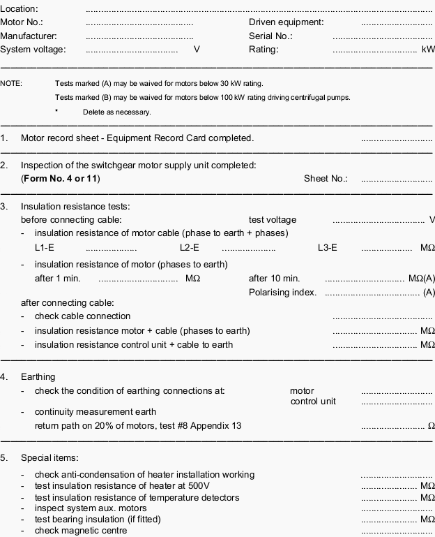
Forms

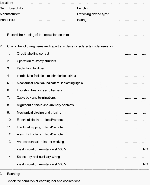
Form 14 – Inspection of electric motor – Cage-induction type (incl. control unit)

Inspection of electric motor cage-induction type (including control unit)

Inspection of electric motor cage-induction type (including control unit)

Form 4 – Inspection of Switching Units – HV Switchgear

Inspection of Switching Units - HV Switchgear

Inspection of Switching Units - HV Switchgear

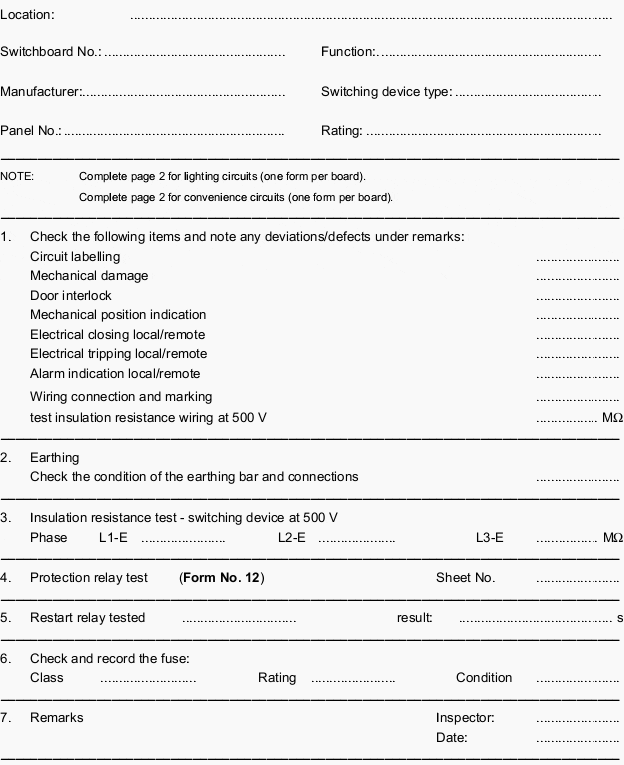
Form 11 – Inspection Of Outgoing Unit – LV Switchboard

Inspection Of Outgoing Unit - LV Switchboard

Inspection Of Outgoing Unit - LV Switchboard


Reference: Field Commissioning and Maintenance Of Electrical Installations and Equipment Manual

4 Motor Designs Identified In NEMA MG1

$
0
0
4 Motor Designs Identified In NEMA MG1

4 Motor Designs Identified In NEMA MG1 (on photo: ABB's three-phase asynchronous electric motors via DirectIndustry.com)

It’s all about performance…

Performance requirements for various types of induction motors for use on standard sinewave power supplies are identified in NEMA MG1. Some of these types of motors are suitable for use in variable speed applications, dependent on the type of application.

Performance requirements are also identified for motors for specific use invariable speed applications.

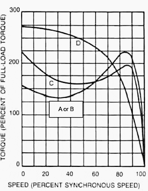
The purpose of this section is to provide guidance on the selection of one or more of the types of motors identified in NEMA MG1 that may be appropriate for the particular variable speed application under consideration. See Figure 1.

Typical motor speed torque curves

Figure 1 - Typical motor speed torque curves


The turning force which a motor develops is known as torque. The amount of torque necessary to start a load (starting torque) is usually different from the torque required to keep the load moving (full load torque).

Loads which have a high breakaway friction or that require extra torque for acceleration, should have a motor specified to have high starting torque.


NEMA motor design A

NEMA MG1 does not impose any limits on the magnitude of the locked-rotor current on Design A motors, other than that the locked-rotor current is greater than the upper limit for Design B motors.

They are usually used in situations where higher locked-rotor current is used for the purpose of obtaining higher running efficiency and higher breakdown torque.

Such motors typically require the use of reduced voltage starting techniques for starting across the standard utility power source. However, normal adjustable frequency control function limits motor operation to the portion of its torque speed characteristic that lies between no-load and breakdown, even during starting.

Because of this, the higher locked rotor current of Design A motors is generally of little concern and the motors are well suited for variable speed operation, exhibiting low slip and high efficiency.

The potentially higher breakdown torque of a Design A motor will extend its constant horsepower speed range beyond that achievable by a Design B motor. However, caution should be used when applying Design A motors in by-pass operation, as their high locked-rotor current can increase starter, thermal overload, and short circuit protection device sizing.

Design A motors may also suffer greater thermal and mechanical stress thanother designs when started across-the-line. Design A motors with very low slip may also exhibit instability under lightly loaded conditions.

NEMA motor design B

Design B motors are applied in variable torque, constant torque and constant horsepower applications.

Adjustable frequency control algorithms are generally optimized to the speed-torque-current characteristics of Design B motors. They exhibit good efficiency and low slip,and are suitable for across-the-line starting in bypass mode.

Design B motors with very low slip may also exhibit instability under lightly loaded conditions.


NEMA motor design C

Design C motor speed-torque-current characteristics were defined to address across-the-line applications requiring high starting(locked-rotor) torque while generally maintaining Design Blocked-rotor current, but slightly higher slip.

Since a Design B motor operated from an adjustable frequency control can provide the same breakaway torque as a Design C motor operated from a control, it is usually preferred because of its industry-standard availability and higher running efficiency. Also, since an adjustable frequency control driven motor normally operates at speeds above the breakdown speed, the high locked-rotor and pull-up torque of a Design C motor serves no benefit in most adjustable speed drive applications.

Because Design C motors usually achieve high starting torque with a double or pseudo-double cage rotor slot, they may exhibit higher rotor losses if the control output current waveform has significant low order harmonic content.

This can result in additional heating in Design C motors over that in Design B and a corresponding greater decrease in system efficiency. Design B motors may not be suitable for bypass operation in an application that normally requires use of a Design C motor for fixed frequency application.


NEMA motor design D

Design D motors were developed specifically for high impact, high starting torque, or high inertia loads.

They exhibit very high locked-rotor torque but suffer in running efficiency due to their high slip characteristic. By employing negative slip compensation with an adjustable frequency control, a Design A, B or C motor can be made to emulate the speed-torque characteristic of a Design D motor while providing higher running efficiency.

As a result, Design D motors are seldom used in general ASD applications.

Design A, B, or C motors cannot be used for bypass operation on an application that normally requires a Design D motor for fixed frequency application.


References
  1. NEMA Standards Publication – Application Guide for AC Adjustable Speed Drive Systems
  2. BALDOR (A member of the ABB Group) – Specifier Guide

Few Words About Stepper Motor (Advantages, Disadvantages and Classification)

$
0
0
Few Words About Stepper Motor (Advantages, Disadvantages and Classification)

Few Words About Stepper Motor (Advantages, Disadvantages and Classification)


Introduction

A stepper motor is an electromechanical device which converts electrical pulses into discrete mechanical movements. The shaft or spindle of a stepper motor rotates in discrete step increments when electrical command pulses are applied to it in the proper sequence.

The motors rotation has several direct relationships to these applied input pulses. The sequence of the applied pulses is directly related to the direction of motor shafts rotation.

The speed of the motor shafts rotation is directly related to the frequency of the input pulses and the length of rotation is directly related to the number of input pulses applied.

Stepper Motor Advantages and Disadvantages

Stepper motor with cable

Stepper motor with cable


Advantages

  1. The rotation angle of the motor is proportional to the input pulse.
  2. The motor has full torque at standstill (if the windings are energized)
  3. Precise positioning and repeatability of movement since good stepper motors have an accuracy of 3 – 5% of a step and this error is non cumulative from one step to the next.
  4. Excellent response to starting/stopping/reversing.
  5. Very reliable since there are no contact brushes in the motor. Therefore the life of the motor is simply dependant on the life of the bearing.
  6. The motors response to digital input pulses provides open-loop control, making the motor simpler and less costly to control.
  7. It is possible to achieve very low speed synchronous rotation with a load that is directly coupled to the shaft.
  8. A wide range of rotational speeds can be realized as the speed is proportional to the frequency of the input pulses.

Disadvantages

  1. Resonances can occur if not properly controlled.
  2. Not easy to operate at extremely high speeds.

Open Loop Operation

One of the most significant advantages of a stepper motor is its ability to be accurately controlled in an open loop system.

Open loop control means no feedback information about position is needed. This type of control eliminates the need for expensive sensing and feedback devices such as optical encoders.

Your position is known simply by keeping track of the input step pulses.


Stepper Motor Types

There are three basic stepper motor types. They are:

  1. Variable-reluctance (VR)
  2. Permanent-magnet (PM)
  3. Hybrid (HB)

Variable-reluctance (VR)

This type of stepper motor has been around for a long time. It is probably the easiest to understand from a structural point of view.

Figure 1 shows a cross section of a typical V.R. stepper motor.

Cross-section of a variable reluctance (VR) motor

Figure 1 - Cross-section of a variable reluctance (VR) motor


This type of motor consists of a soft iron multi-toothed rotor and a wound stator. When the stator windings are energized with DC current the poles become magnetized. Rotation occurs when the rotor teeth are attracted to the energized stator poles.

Permanent Magnet (PM)

Often referred to as a “tin can” or “canstock” motor the permanent magnet step motor is a low cost and low resolution type motor with typical
step angles of 7.5°to 15°.

Principle of a PM or tin-can stepper motor

Figure 2 - Principle of a PM or tin-can stepper motor


(48 – 24 steps/revolution) PM motors as the name implies have permanent magnets added to the motor structure.

The rotor no longer has teeth as with the VR motor. Instead the rotor is magnetized with alternating north and south poles situated in a straight line parallel to the rotor shaft.

These magnetized rotor poles provide an increased magnetic flux intensity and because of this the PM motor exhibits improved torque characteristics when compared with the VR type.


Hybrid (HB)

The hybrid stepper motor is more expensive than the PM stepper motor, but provides better performance with respect to step resolution, torque and speed.

Cross-section of a hybrid stepper motor

Figure 3 - Cross-section of a hybrid stepper motor


Typical step angles for the HB stepper motor range from 3.6°to 0.9° (100 – 400 steps per revolution).

The hybrid stepper motor combines the best features of both the PM and VR type stepper motors.

The rotor is multi-toothed like the VR motor and contains an axially magnetized concentric magnet around its shaft. The teeth on the rotor provide an even better path which helps guide the magnetic flux to preferred locations in the airgap. This further increases the detent, holding and dynamic torque characteristics of the motor when compared with both the VR and PM types.

The two most commonly used types of stepper motors are the permanent magnet and the hybrid types.


Make the right choice

If a designer is not sure which type will best fit his applications requirements he should first evaluate the PM type as it is normally several times less expensive. If not then the hybrid motor may be the right choice.

There also excist some special stepper motor designs. One is the disc magnet motor. Here the rotor is designed sa a disc with rare earth magnets, see figure 4 .

This motor type has some advantages such as very low inertia and a optimized magnetic flow path with no coupling between the two stator windings.
Principle of a disc magnet motor developed by Portescap

Figure 4 - Principle of a disc magnet motor developed by Portescap


These qualities are essential in some applications.


How the Stepper motors are made and how they operate (1)

Cant see this video? Click here to watch it on Youtube.


How the Stepper motors are made and how they operate (2)

Cant see this video? Click here to watch it on Youtube.

Reference: Industrial Circuits Application Note – Stepper Motor Basics by PAControl.com

Identity Card of Every Asynchronous Motor

$
0
0
Identity Card of Every Asynchronous Motor

Identity Card of Every Asynchronous Motor (on photo: ABB AC motor in top lift; by Melissa Blair, BaldorPowerWI via Flickr)


Motor parameters

A motor is characterized by different electrical and constructional parameters which identify its correct application field.

The whole of all these parameters constitutes the rating of the machine and is reported on a nameplate positioned on the motor itself.

Hereunder is a short description of the main parameters included in the nameplate rating with simple information about the electrical parameters which are the most known ones and those more easily explained, whereas particular attention is paid to those which are less common and refer to working and environmental conditions.

The electrical and mechanical parameters which constitute the rating of a motor identify its rated performances and are:


1. The power in kW

The power in kW, which represents the rated mechanical power made available by the shaft; in many countries it is common to express the available mechanical power of the motor shaft also in horsepower:

  • 1hp (UK and US horsepower) is equivalent to 745.7W
  • 1hp (metric horsepower) is equivalent to 736W

2. The supply voltage of the motor

The supply voltage of the motor, e.g. 230VΔ, 400VY.

With a three-phase distribution system at 400V (phase-to-neutral voltage 230V, phase-to-phase voltage 400Vthe motor can be only star-connected. In case of delta connection the motor windings would be subject to 400V, when they have been dimensioned for 230V.

As a consequence, the considered motor does not result suitable for connection to the network in the example with delta-connected windings.

To summarize:

A motor having double operating voltage could be used in the following configurations:

  1. Windings with delta-connection only supplied at the lower voltage;
  2. Windings with star-connection only supplied at the higher voltage);
  3. Windings with Y/Δconnection (with six conductors to the motor) with Y configuration at motor starting and Δ configuration during motor running, possible when the lower value of the rated voltage of the motor coincides with the voltage of the supply;
  4. The rated current linked to the power and to the voltage through the rated efficiency parameters “η” and the power factor “cosϕ”;
  5. The rotation speed in rpm linked to the frequency (50Hz or 60Hz) and to the number of poles.

The other information on the nameplate, with a meaning less clear or not easily recognizable, are referred to:


1. Duty type:

To be declared by the purchaser of the motor (classifications given by the Std. IEC 60034-1 “Rotating electrical machines. Part 1: “Rating and performance”) and necessary to define the rating that the motor must guarantee according to the application type.

Where a duty is not declared, the manufacturer shall assume that duty type S1 (continuous running duty) applies. For a thorough analysis on duty types, please refer to Annex D;


2. Degree of protection (IP code classification):

It indicates the degree of protection provided by the enclosures of electrical rotating machines (prescriptions and classification complying with the Std. IEC 60034-5 Part 5: “Degrees of protection provided by the integral design of rotating electrical machines”).

The first characteristic numeral indicates the degree of protection provided by the enclosure both to persons as well as to the parts of the machine inside the enclosure. It gives information about protection against approach to or contacts with live parts and against contact with moving parts inside the enclosure and protection of the machine against ingress of solid foreign objects.

The second characteristic numeral indicates the degree of protection provided by the enclosure with respect to harmful effects due to ingress of water.


3. Thermal class:

It indicates the temperature limits for motor windings.

It is expressed through insulation classes identified by letters, to which the maximum permitted temperature for the windings is associated as represented in Table 1.

Systems with insulation class F are often used; for them a temperature rise referred to thermal class B is allowed, which guarantees a margin of safety on the insulation life.

Table 1 – References for thermal class and relevant temperature

Thermal classTemperature class
A105
E120
B130
F155
H180

Other codes which allow to go further into details on motor typology, but which result to be quite complex to intepret and relevant to problems not closely connected to the purpose of this technical paper may be:


4. IC code:

It is a designation relevant to the methods of cooling and is formed by numerals and letters representing the circuit arrangement, the coolant and the methods of movement of the coolant itself.

For further details please refer to the Std. IEC 60034-6 “Rotating electrical machines. Part 6: Methods of cooling”.


5. IM code:

It is a designation relevant to the classifications of types of constructions (arrangement of machine components with regard to fixings, bearing arrangement and shaft extensions) and mounting arrangements (orientation on site of the machine as the whole with regard to shaft alignment and position of fixings) of rotating electrical machines.

For further details please refer to the Std. IEC 60034-7 “Rotating electrical machines. Part 7: Classification of types of constructions and mounting arrangements (IM Code)”.

Reference: ABB technical application paper – Three-phase asynchronous motors Generalities and ABB proposals for the coordination of protective devices

Heat as one of the most common cause of motor failure

$
0
0
Heat as one of the most common cause of motor failure

Heat as one of the most common cause of motor failure (on photo: burned motor windings due to the overheating; by hybridperformance.blogspot.com)

Service life

Heat is the most common cause of motor failure before reaching rated service life.

Every increase of 10 degrees Centigrade of a motor’s windings above its design operating temperature cuts the life of the motor’s windings insulation by 50 percent, even if the overheating was only temporary.

Overheating arises from a number of factors.

If a motor is undersized for an application, or if a manager selects a motor with the wrong starting current and torque characteristics, it will operate warmer than its design temperature. Managers should always match all motors to their connected loads.

While undersizing leads to overheating, oversizing lowers the application’s energy efficiency.

A number of universal factors come into play when you deal with operating temperatures, no matter what the application.

These include:

  • The electrical efficiency of the motor in question;
  • The ambient temperature for which the motor is rated;
  • The ambient temperature in which it will operate;
  • The temperature rise the motor will undergo when it is working as well as its nameplate rated temperature rise;
  • The class of electrical insulation with which the motor is made; and
  • The motor’s service factor.

Hot environment

Another common cause of overheating is operating the motor in an environment with a high ambient temperature, which reduces the rate at which heat can be conducted from the motor.

This condition results in higher-than-rated winding temperatures and shortened service lives.

Locating motors in inadequately ventilated areas or close to heat-producing equipment can easily result in ambient temperatures high enough to cause damage.

Technicians should it file temperature in areas where motors are installed, adding forced ventilation if temperatures exceed the ratings for a motor. Even if the ambient temperature is within the manufacturer’s guidelines, plugged air passage, blocked cooling fans, and dirty cooling vanes will result in elevated motor operating temperatures.

Managers should make sure technicians inspect motors at least annually to ensure that their cooling components are clear.

Enclosed motor

Enclosed motor (on photo: Baldor Single Phase Totally Enclosed General Purpose Motors)


If the motor is enclosed (in a furnace, for example, or within a protective housing such as a pump housing), the ambient temperature that motor experiences is actually the temperature of the air immediately surrounding the enclosure. This suggests you will have to consider dissipating the temperature within the enclosure by passive or positive ventilation.

If you are comparing an enclosed motor with a similarly rated open and ventilated motor, you will need to consider the difficulty involved in dissipating the heat involved in the operation of the enclosed motor.

References:

  • James Piper, Maintenance Solutions
  • Beating the Heat, Century

Calculating the short-circuit current across the terminals of a synchronous generator

$
0
0
Calculating the short-circuit current across the terminals of a synchronous generator

Calculating the short-circuit current across the terminals of a synchronous generator

Alternators and motors

Calculating the short-circuit current across the terminals of a synchronous generator is very complicated because the internal impedance of the latter varies according to time.

When the power gradually increases, the current reduces passing through three characteristic periods:

  1. Subtransient (enabling determination of the closing capacity of circuit breakers and electrodynamic contraints), average duration, 10 ms
  2. Transient (sets the equipment’s thermal contraints), average duration 250 ms
  3. Permanent (this is the value of the short-circuit current in steady state).
The short-circuit current is calculated in the same way as for transformers but the different states must be taken account of.
Short-circuit current - three characteristic periods

Short-circuit current – three characteristic periods


The short-circuit current is given by the following equation:

Isc = Ir / Xsc

Xsc - Short-circuit reactance c/c

The most common values for a synchronous generator are:

StateSubtransient X”dTransient X’dPermanent Xd
Xsc10 – 20%15 – 25%200 – 350%

Example

Calculation method for an alternator or a synchronous motor.

  • Alternator 15 MVA
  • Voltage U = 10 kV
  • X’d = 20%

Short-circuit calculation example

All electrical installations have to be protected against short-circuits, without exception, whenever there is an electrical discontinuity; which more generally corresponds to a change in conductor cross-section.

The short-circuit current shall be calculated at each stage in the installation for the various configurations that are possible within the network, in order to determine the characteristics of the equipment that has to withstand or break this fault current.

Reference: Medium voltage design guide – Schneider Electric

Inspection and test procedures for Rotating Machinery, Synchronous Motors and Generators

$
0
0
Inspection and test procedures of Rotating Machinery, Synchronous Motors and Generators

Inspection and test procedures of Rotating Machinery, Synchronous Motors and Generators (On photo: Small machine test set – ee.polyu.edu.hk)

Procedures (Index)

  1. Visual and Mechanical Inspection
  2. Electrical Tests
  3. Test Values
    1. Visual and Mechanical Tests
    2. Electrical Tests
  4. Pictures:
    1. Electrical machine wired for electrical testing
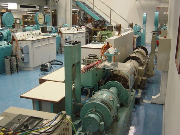
    2. The Electrical Machines Laboratory
  5. TABLE 100.10 – Maximum Allowable Vibration Amplitude
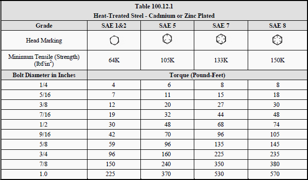
  6. TABLE 100.12 – US Standard Fasteners

1. Visual and Mechanical Inspection

  1. Compare equipment nameplate datawith drawings and specifications.
  2. Inspect physical and mechanical condition.
  3. Inspect anchorage, alignment, and grounding.
  4. Inspect air baffles, filter media, cooling fans, slip rings, brushes, and brush rigging.
  5. Inspect bolted electrical connections for high resistance using one or more of the following?methods:
    1. Use of low-resistance ohmmeter?in accordance with procedure for LR ohmmeter?usage.
    2. Verify tightness of accessible bolted electrical connections by calibrated torque-wrench?method in accordance with manufacturer?s published data or Table 100.12?(see below).
    3. Perform thermographic survey.
  6. Perform special tests such as air-gap spacing and machine alignment.
  7. Verify the application of appropriatelubrication and lubrication systems.
  8. Verify that resistance temperature detector (RTD) circuits conform to drawings.

Go to Index ↑


2. Electrical Tests

  1. Perform resistance measurements through bolted connections with a low-resistance ohmmeter,?if applicable.
  2. Perform insulation-resistance tests inaccordance with ANSI/IEEE Standard 43.
    1. Machines larger than 200 horsepower (150 kilowatts):
      Test duration shall be for ten minutes. Calculate polarization index.
    2. Machines 200 horsepower (150 kilowatts) and less:
      Test duration shall be for one minute. Calculate dielectric-absorption ratio.
  3. Perform dc dielectric withstand voltage tests on machines rated at 2300 volts and greater in?accordance with ANSI/IEEE Standard 95.
  4. Perform phase-to-phase stator resistance test on machines 2300 volts and greater.
  5. ** Perform insulation power-factoror dissipation-factor tests.
  6. ** Perform power-factor tip-up tests.
  7. ** Perform surge comparison tests.
  8. Perform insulation-resistance test on insulated bearings in accordance with manufacturer?s?published data, if applicable.
  9. Test surge protection devices.
  10. Test motor starter.
  11. Perform resistance tests on resistance temperature detector (RTD) circuits.
  12. Verify operation of machine space heater, if applicable.
  13. ** Perform vibration test.
  14. Perform insulation-resistance tests on the main rotating field winding, the exciter-field winding, and the exciter-armature winding in accordance with ANSI/IEEE Standard 43.
  15. ** Perform an ac voltage-drop test on all rotating field poles.
  16. ** Perform a high-potential test on the excitation system in accordance with ANSI/IEEE Standard?421.3.
  17. Measure resistance of machine-field winding, exciter-stator winding, exciter-rotor windings,?and field discharge resistors.
  18. ** Perform front-to-back resistance tests on diodes and gating tests of silicon-controlled rectifiers?for field application semiconductors.
  19. Prior to re-energizing, apply voltage to the exciter supply and adjust exciter-field current to?nameplate value.
  20. Verify that the field application timer and the enable timer for the power-factor relay have been?tested and set to the motor drive manufacturer?s recommended values.
  21. ** Record stator current, stator voltage, and field current for the complete acceleration period?including stabilization time for a normally loaded starting condition. From the recording?determine the following information:
    1. Bus voltage prior to start.
    2. Voltage drop at start.
    3. Bus voltage at machine full-load.
    4. Locked-rotor current.
    5. Current after synchronization but before loading.
    6. Current at maximum loading.
    7. Acceleration time to near synchronous speed.
    8. Revolutions per minute (RPM) just prior to synchronization.
    9. Field application time.
    10. Time to reach stable synchronous operation.
  22. ** Plot a V-curve of stator current versus excitation current at approximately 50 percent load to?check correct exciter operation.
  23. ** If the range of exciter adjustment and machine loading permit,reduce excitation to cause power?factor to fall below the trip value of the power-factor relay. Verify relay operation.

** OPTIONAL

Go to Index??


3. Test Values

3.1 Visual and Mechanical Test Values

  1. Inspection:
    1. Air baffles shall be clean and installed in accordance with manufacturer?s published?data.
    2. Filter media shall be clean and installed in accordance with manufacturer?s published?data.
    3. Cooling fans shall operate.
    4. Slip ring alignment shall be within manufacturer?s published tolerances.
    5. Brush alignment shall be within manufacturer?s published tolerances.
    6. Brush rigging shall be in accordance with manufacturer?s published data.
  2. Compare bolted connection resistance values to values of similar connections. Investigate any?values that deviate from similar bolted connections by more than 50 percent of the lowest?value.
  3. Bolt-torque levels should be in accordance with manufacturer?s published data. In the absence?of manufacturer?s published data, use Table 100.12 (see below)
  4. Results of thermographic survey to be analysed.
  5. Air-gap spacing and machine alignment shall be in accordance with manufacturer?s published?data.

Go to Index??


3.2 Electrical Test Values

  1. Compare bolted connection resistance values tovalues of similar connections. Investigate any?values that deviate from similar bolted connections by more than 50 percent of the lowest?value.
  2. The dielectric absorption ratio or polarization index shall not be less than 1.0. The?recommended minimum insulation resistance (IR 1 min) test results in megaohms shall be?corrected to 40? C and read as follows:
    1. IR 1 min = kV + 1 for most windings made before 1970 (kV is the rated machine terminal-to-terminal voltage in rms kV)
    2. IR 1 min = 100 megohms for most dc armatureand ac windings built after 1970 (form-wound coils).
    3. IR 1 min = 5 megohms for most machines and random-wound stator coils and form-wound coils rated below 1 kV.
      -
      NOTE: Dielectric withstand voltage and surge comparison tests shall not be performed?on machines having values lower than those indicated above.
  3. If no evidence of distress or insulation failure is observed by the end of the total time of voltage?application during the dielectric withstand test, the test specimen is considered to have passed?the test.
  4. Investigate phase-to-phase stator resistance values that deviate by more than five percent.
  5. Power-factor or dissipation-factor values shall be compared to manufacturer?s published data.?In the absence of manufacturer?s published data these values will be compared with previous?values of similar machines.
  6. Tip-up values shall indicate no significant increase in power factor.
  7. If no evidence of distress, insulation failure, orlack of waveform nesting is observed by the end?of the total time of voltage application during the surge comparison test, the test specimen is?considered to have passed the test.
  8. Insulation resistance of bearings shall be within manufacturer?s published tolerances. In the?absence of manufacturer?s published tolerances, the comparison shall be made to similar?machines.
  9. Test results of surge protection devices shall be in accordance with procedures for testing of LV surge arresters.
  10. Test results of motor starter equipment shall be in accordance with?procedures for testing of motor starter equipment.
  11. RTD circuits shall be in accordance with system design intent and machine protection device?manufacturer?s published data.
  12. Heaters shall be operational.
  13. Vibration amplitudes of the uncoupled and unloaded machine shall not exceed values shown in?Table 100.10 (see below). If values exceed, perform complete vibration analysis.
  14. The recommended minimum insulation resistance (IR1 min) test results in megaohms shall be?corrected to 40? C and read as follows:
    1. IR 1 min= kV + 1 for most windings made before 1970, all field windings (kV is the rated machine terminal-to-terminal voltage in rms kV)
    2. IR 1 min= 100 megohms for most dc armature and ac windings built after 1970 (form-wound coils).
    3. IR 1 min= 5 megohms for most machines and random-wound stator coils and form-wound coils rated below 1 kV.
      -
      NOTE: Dielectric withstand voltage, high-potential, and surge comparison tests shall?not be performed on machines having values lower than those indicated above.
  15. The pole-pole AC voltage drop shall not exceed 10 percent variance between poles.
  16. If no evidence of distress or insulation failure is observed by the end of the total time of voltage?application during the dielectricwithstand test, the winding is considered to have passed the?test.
  17. The measured resistance values of motor-field windings, exciter-stator windings, exciter-rotor?windings, and field-discharge resistors shall be compared to manufacturer?s published data. In?the absence of manufacturer?spublished data, the comparison shall be made to similar?machines.
  18. Resistance test results of diodes and gating tests of silicon-controlled rectifiers shall be in?accordance with industry standards and system design requirements.
  19. Exciter power supply shall allow exciter-field current to be adjusted to nameplate value.
  20. Application timer and enable timer for power-factor relay test results shall comply with?manufacturer?s recommended values.
  21. Recorded values shall be in accordance with system design requirements.
  22. Plotted V-curve shall indicate correct exciter operation.
  23. When reduced excitation falls below trip value for the power-factorrelay, the relay shall?operate.

Go to Index ↑


Electrical machine wired for electrical testing

Electrical machine wired for electrical testing (photo credit: komel.katowice.pl)

Electrical machine wired for electrical testing (photo credit: komel.katowice.pl)


Go to Index ↑


The Electrical Machines Laboratory

The Electrical Machines Laboratory (photo credit: ee.polyu.edu.hk)

The Electrical Machines Laboratory (photo credit: ee.polyu.edu.hk)


Go to Index ↑


TABLE 100.10

Maximum Allowable Vibration Amplitude

Table 100.10 - Maximum Allowable Vibration Amplitude

Table 100.10 – Maximum Allowable Vibration Amplitude


Go to Index ↑


TABLE 100.12

US Standard Fasteners – Bolt-Torque Values for Electrical Connections

Table 100.12.1 - Heat-Treated Steel - Cadmium or Zinc Plated

Table 100.12.1 – Heat-Treated Steel – Cadmium or Zinc Plated


Table 100.12.2 - Silicon Bronze Fasteners

Table 100.12.2 – Silicon Bronze Fasteners


Table 100.12.3 - Aluminum Alloy Fasteners

Table 100.12.3 – Aluminum Alloy Fasteners


Table 100.12.4 - Stainless Steel Fasteners

Table 100.12.4 – Stainless Steel Fasteners


a. Consult manufacturer for equipment supplied with metric fasteners.
b. This table is based on bronze alloy bolts having a minimum tensile strength of 70,000 pounds per square inch.
c. This table is based on aluminum alloy bolts having a minimum tensile strength of 55,000 pounds per square inch.
d. This table is to be used for the following hardware types:

  • Bolts, cap screws, nuts, flat washers, locknuts (18?8 alloy)
  • Belleville washers (302 alloy).

Go to Index ↑


Reference:?ANSI/NETA Standard for Acceptance Testing Specifications for Electrical Power Equipment and Systems

Physical Structure & Configuration of DC Machines

$
0
0
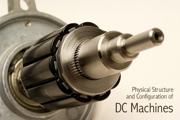
Physical structure and configuration of DC Machines

Physical structure and configuration of DC Machines

Two-pole machine

Figure 1 depicts a two-pole machine in which the stator poles are constructed in such a way as to project closer to the rotor than to the stator structure. This type of construction is rather common, and poles constructed in this fashion are called salient poles.

Note that the rotor could also be constructed to have salient poles.

Figure 0 - Cross section of DC machine

Figure 0 – Cross section of DC machine

Direct Current Motor (Rotor, Startor)

A representative DC machine was depicted in Figure 0 above, with the magnetic poles clearly identified, for both the stator and the rotor.

Figure 1 is a photograph of the same type of machine. Note the salient pole construction of the stator and the slotted rotor. As previously stated, the torque developed by the machine is a consequence of the magnetic forces between stator and rotor poles.

This torque is maximum when the angle γ between the rotor and stator poles is 90◦.

Also, as you can see from the figure, in a DC machine the armature is usually on the rotor, and the field winding is on the stator.


DC motor parts

Figure 1 - DC machine

Figure 1 – DC machine


To keep this torque angle constant as the rotor spins on its shaft, a mechanical switch, called a commutator, is configured so the current distribution in the rotor winding remains constant, and therefore the rotor poles are consistently at 90◦ with respect to the fixed stator poles.

In a DC machine, the magnetizing current is DC, so that there is no spatial alternation of the stator poles due to time-varying currents.

To understand the operation of the commutator, consider the simplified diagram of Figure 4. In the figure, the brushes are fixed, and the rotor revolves at an angular velocity ωm; the instantaneous position of the rotor is given by the expression: θ = ωmt − γ.

The commutator is fixed to the rotor and is made up in this example of six segments that are made of electrically conducting material but are insulated from one another. Further, the rotor windings are configured so that they form six coils, connected to the commutator segments as shown in Figure 4.

Figure 4 - Rotor winding and commutator

Figure 4 – Rotor winding and commutator


As the commutator rotates counterclockwise, the rotor magnetic field rotates with it up to θ = 30◦. At that point, the direction of the current changes in coils L3 and L6 as the brushes make contact with the next segment.

Now the direction of the magnetic field is −30◦. As the commutator continues to rotate, the direction of the rotor field will again change from −30◦ to +30◦, and it will switch again when the brushes switch to the next pair of segments. In this machine, then, the torque angle γ is not always 90◦, but can vary by as much as ±30◦; the actual torque produced by the machine would fluctuate by as much as ±14 percent, since the torque is proportional to sin γ.

As the number of segments increases, the torque fluctuation produced by the commutation is greatly reduced. In a practical machine, for example, one might have as many as 60 segments, and the variation of γ from 90◦ would be only ±3◦, with a torque fluctuation of less than 1 percent.

Thus, the DC machine can produce a nearly constant torque (as a motor) or voltage (as a generator).


Configuration of DC Machines

Figure 5 - Configuration of DC Machines

Figure 5 – Configuration of DC Machines

In DC machines, the field excitation that provides the magnetizing current is occasionally provided by an external source, in which case the machine is said to be separately excited [Figure 5 (a)]. More often, the field excitation is derived from the armature voltage, and the machine is said to be self-excited.

The latter configuration does not require the use of a separate source for the field excitation and is therefore frequently preferred. If a machine is in the separately excited configuration, an additional source Vf is required. In the self-excited case, one method used to provide the field excitation is to connect the field in parallel with the armature; since the field winding typically has significantly higher resistance than the armature circuit (remember that it is the armature that carries the load current), this will not draw excessive current from the armature.

Further, a series resistor can be added to the field circuit to provide the means for adjusting the field current independent of the armature voltage. This configuration is called a shunt-connected machine and is depicted in Figure 5 (b).

Another method for self-exciting a DC machine consists of connecting the field in series with the armature, leading to the series-connected machine, depicted in Figure 5 (c); in this case, the field winding will support the entire armature current, and thus the field coil must have low resistance (and therefore relatively few turns).

This configuration is rarely used for generators, since the generated voltage and the load voltage must always differ by the voltage drop across the field coil, which varies with the load current.

Thus, a series generator would have poor (large) regulation.

However, series-connected motors are commonly used in applications not more than about 1 kW output, or if we are talking about bigger motors – they are used for electric locomotives.

The third type of DC machine is the compound-connected machine, which consists of a combination of the shunt and series configurations. Figure 5 (d) and (e) shows the two types of connections, called the short shunt and the long shunt, respectively.

Each of these configurations may be connected so that the series part of the field adds to the shunt part (cumulative compounding) or so that it subtracts (differential compounding).


Reference:

Fundamentals of electrical engineering by Giorgio Rizzoni, The Ohio State University (purchase paperback from Amazon)

Motor Starting via Chokes or Resistors

$
0
0
Motor Starting via Chokes or Resistors

Motor Starting via Chokes or Resistors

Reducing the voltage and starting current

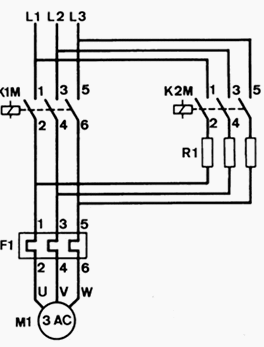
The series-connected chokes (Figure 1) or resistors (Figure 2) reduce the voltage at the motor and hence also the starting current. The starting torque is reduced by around the square of the current.


Starting via chokes

At rest the motor impedance is small. Most of the supply voltage drops across the series-connected chokes.

The breakaway torque of the motor is therefore strongly reduced.

With increasing speed, the voltage across the motor increases because of the fall of the current consumption and the vectorial voltage distribution between the motor and the reactance connected in series.

Motor starting via series-connected chokes

Figure 1 – Motor starting via series-connected chokes


Hence the motor torque also increases. After the motor start-up, the chokes are shorted by the time-delayed main contactor K1M and the starting contactor K2M is dropped out.


Starting via resistors

The basic circuit diagram is the basically the same as described above, with only difference that the chokes are replaced by lower-cost resistors.

Motor starting via series-connected resistors

Figure 2 – Motor starting via series-connected resistors


With this method, the starting current can only be slightly reduced, as the motor torque falls with the square of the voltage and the voltage across the motor, other than with starting via chokes, only increases slightly with increasing speed. It is more advantageous to reduce the series-resistance during starting in steps.

This reduces the voltage across the resistor and increases that across the motor. The expenditure on hardware is thereby significantly larger.

A simpler solution are enclosed electrolytic resistors with a negative temperature coefficient. Their ohmic resistance decreases automatically during starting because of heating by the starting current.

Reference: Low voltage switchgear and control gear application guide – A technical reference handbook for electrical engineers by NHP


PLC application for reduced voltage-start motor control

$
0
0
PLC application for reduced voltage-start motor control

PLC application for reduced voltage-start motor control (photo credit: plctalk.net)

Reduced-voltage-start motor control circuit

Figure 1 shown below illustrates the control circuit and wiring diagram of a 65% tapped, autotransformer, reduced-voltage-start motor control circuit. This reduced voltage start minimizes the inrush current at the start of the motor (locked rotor current) to 42% of that at full speed.

In this example, the timer must be set to 5.3 seconds. Also, the instantaneous contacts from the timer in lines 2 and 3 must be trapped.

(a) Hardwired relay circuit and (b) wiring diagram of a reduced-voltage-start motor

Figure 1 – (a) Hardwired relay circuit and (b) wiring diagram of a reduced-voltage-start motor

Hardwired circuit (real I/O)

Figure 2 illustrates the hardwired circuit with the real inputs and outputs circled. The devices that are not circled are implemented inside the PLC through the programming of internal instructions.

Real inputs and outputs to the PLC

Figure 2 – Real inputs and outputs to the PLC


Tables 1, 2, and 3 show the I/O assignment, internal assignment, and register assignment, respectively.

Figure 3 illustrates the PLC implementation of the reduced-voltage start circuit. The first line of the PLC program traps the timer with internal output 1000. Contacts from this internal replace the instantaneous timer contacts specified in the hardwired control circuit. This PLC circuit implementation does not provide low-voltage protection, since the interlocking does not use the physical inputs of M1, S1, and S2.

Table 1 – I/O address assignment

I/O Address
Module TypeRackGroupTerminalDescription
 Input000 Stop PB (NC)
001 Stop PB (NO)
 Output030 Motor Starter M1
031 S1
032 S2

Table 2 – Internal address assignment

DeviceInternalDecription
 —1000 Trap Timer Circuit
 Timer1001 Timer

Table 3 – Register assignment

RegisterDecription
 4000 Preset register value 53, time base 0.1 sec. for 5.3 sec. (timer output is 1001)
 4001 Accumulated register for timer output 1001

PLC implementation of the circuit in Figure 1

Figure 3 – PLC implementation of the circuit in Figure 1

If low-voltage protection is required, then the starter’s auxiliary contacts or the overload contacts can be programmed.

If the auxiliary contacts or the overloads are used as inputs, they must be programmed as normally open (closed when the overloads are closed and the motor is running) and placed in series with contact 1000 in line 3 of the PLC program.

If the overloads open, the circuit will lose continuity and M1 will turn OFF.

Resource: Introduction-to-PLC-Programming – www.globalautomation.info

How to measure insulation resistance of a motor

$
0
0
How to measure insulation resistance of a motor

How to measure insulation resistance of a motor (photo credit: elecls.cc.oita-u.ac.jp)

Winding insulation resistance

If the motor is not put into operation immediately upon arrival, it is important to protect it against external factors like moisture, high temperature and impurities in order to avoid damage to the insulation. Before the motor is put into operation after a long period of storage, you have to measure the winding insulation resistance.

If the motor is kept in a place with high humidity, a periodical inspection is necessary.

It is practically impossible to determine rules for the actual minimum insulation resistance value of a motor because resistance varies according to method of construction, condition of insulation material used, rated voltage, size and type. In fact, it takes many years of experience to determine whether a motor is ready for operation or not.

A general rule-of-thumb is 10 Megohm or more.

 Insulation resistance value Insulation level
 2 Megohm or less Bad
 2-5 Megohm Critical
 5-10 Megohm Abnormal
 10-50 Megohm Good
 50-100 Megohm Very good
 100 Megohm or more Excellent

The measurement of insulation resistance is carried out by means of a megohmmeter – high resistance range ohmmeter. This is how the test works: DC voltage of 500 or 1000 V is applied between the windings and the ground of the motor.

Ground insulation test of a motor

Ground insulation test of a motor


During the measurement and immediately afterwards, some of the terminals carry dangerous voltages and MUST NOT BE TOUCHED.

Now, three points are worth mentioning in this connection: Insulation resistance, Measurement and Checking.


1. Insulation resistance

  • The minimum insulation resistance of new, cleaned or repaired windings with respect to ground is 10 Megohm or more.
  • The minimum insulation resistance, R, is calculated by multiplying the rated voltage Un, with the constant factor 0.5 Megohm/kV.

    For example: If the rated voltage is 690 V = 0.69 kV, the minimum insulation resistance is: 0.69 kV x 0.5 Megohm/kV = 0.35 Megohm

2. Measurement

  • Minimum insulation resistance of the winding to ground is measured with 500 V DC. The winding temperature should be 25°C ± 15°C.
  • Maximum insulation resistance should be measured with 500 V DC with the windings at a operating temperature of 80 – 120°C depending on the motor type and efficiency.

3. Checking

  • If the insulation resistance of a new, cleaned or repaired motor that has been stored for some time is less then 10 Mohm, the reason might be that the windings are humid and need to be dried.
  • If the motor has been operating for a long period of time, the minimum insulation resistance may drop to a critical level. As long as the measured value does not fall below the calculated value of minimum insulation resistance, the motor can continue to run.

    However, if it drops below this limit, the motor has to be stopped immediately, in order to avoid that people get hurt due to the high leakage voltage.

Reference: Grudfos – Motor Book

A Few Words About Selecting AC Induction Motors for Cement Plant Applications

$
0
0
Few Words About Selecting AC Induction Motors for Cement Plant Applications (on photo:3,500 kW ball-mill drive for a cement plant in England via emz.de)

Few Words About Selecting AC Induction Motors for Cement Plant Applications (on photo:3,500 kW ball-mill drive for a cement plant in England via emz.de)

Introduction

This technical article relies on the great paper written by Barton J. Sauer (Siemens Energy & Automation) which goes into essence of selecting the proper AC motor for cement plant applications.

Although motors may appear to be the least complicated component in the specification of cement mill equipment, this article shall try to demonstrate that cement plant applications present an immense matrix of application criteria to properly specify and design motors.

To obtain the correct motor for the specific job, communication, expectations and knowledge must be exchanged between the mill operator, driven equipment suppler and motor manufacturer.

Operating Conditions

Basic motor specifications begin with determining the motor nameplate hp and rpm. These are determined by the process equipment supplier and are based upon a steady state equipment operation.

Next is the determination of the available power voltage.

The cement plant operator, process equipment supplier or engineering consulting firm must determine the most effective power source, taking load hp and amp values of the entire system into consideration.

The Hz rating is determined by the power system available at the site. Because the cement market is global with many Hz and voltage combinations, the Hz value cannot be assumed. It is important to the motor manufacturer in the proper design of a motor, which would be different for Chile (50 Hz) than Argentina (60 Hz).

SIEMENS induction motor nameplate

SIEMENS induction motor nameplate (photo credit: forums.mikeholt.com)


Ambient temperature is often overlooked as a design criteria.

Ambient temperatures below –30° C can require special bearing lubricant and material requirements. Conversely, ambient temperatures above 40° C may result in the allowable motor temperature rise to be lowered, which effectively de-rates the motor output.

The altitude at the site can also affect the motor selection when installation elevations exceed 1000 meters.

The lower density of air at higher altitudes results in a decreased cooling media for the motor. The derate factor is 1% of the specified temperature rise for each 100 meters of altitude in excess of 1000 meters.


Driven Equipment Torque Requirements

To properly select AC induction motors for any application, the speed vs. torque requirements of the driven equipment must be understood. It is an easy mistake to believe that a 400 hp 1200 rpm motor, which would function well in a low inertia fan application, would also work aptly in a kiln application.

However, the load torque requirements of a fan pump during initial starting are typically less than 30% of full load torque, while a full kiln could have load torque requirements of over 100% of full load torque.

The distinction must be understood between the running condition of the driven equipment, which dictate the hp and rpm of the motor, and the starting load condition of the driven equipment, which dictates the motor starting characteristics.

The National Electrical Manufactures Association (NEMA) classifies the torque characteristics of motors as follows:

// Locked-rotor Torque (LRT)

The minimum torque which the motor will develop at rest…with rated voltage”, expressed as a percentage of rated full load torque the motor generates at initial rotation of motor shaft

// Pull-up Torque (PUT)

The lowest percentage of rated full load torque the motor generates during starting.

// Breakdown Torque (BDT)

The highest percentage of rated full load torque the motor generates prior to reaching full load speed.

Motors that do not have sufficient starting torque for the driven equipment will stall during starting.

A stall condition requires the mine operator to lower the starting load before attempting to restart the equipment. In the case of crushers or mills, this means the removal of aggregate from the machine. Excessive stall conditions also damage the motor due to excessive current flow in the stator and rotor.


Design Specs // Motor Enclosure

The motor enclosure defines the degree of protection for the motor windings. The selection of the motor enclosure is typically left to the discretion of parties other than the motor manufacturer.

However, the motor manufacturer can choose to provide an enclosure that exceeds the requirements of that specified by the purchaser.

1. Totally Enclosed Fin-Cooled Motor (TEFC)

Totally enclosed fan cooled is the most common enclosure for the cement industry.

A totally enclosed machine is one so enclosed as to prevent the free exchange of air between the inside and the outside of the case but not sufficiently enclosed to be termed air-tight.

Totally Enclosed Air-to-Air Cooled Motor (TEAAC)

Figure 1 – Totally Enclosed Air-to-Air Cooled Motor (TEAAC)


The two major types of TEFC motors are totally enclosed fin cooled and totally enclosed air to air cooled (TEAAC – Figure 1 above). The fin cooled (Figure 2) variant is defined by the cooling fins that cover the main structure of the enclosure.

Totally Enclosed Fin-Cooled Motor

Figure 2 – Totally Enclosed Fin-Cooled Motor


Typically this frame is constructed of cast iron, although welded steel fin and aluminum cast construction is occasionally offered. TEAAC motors are equipped with an air to air heat exchanger on the top of the motor stator. In a TEAAC enclosure, the hot air from the stator is forced around the tubes that channel the cooling air.

Available tube materials on TEAAC motors include aluminum, copper and stainless steel, as appropriate for the environmental conditions.

Open Enclosures: Open type enclosures present a lower cost option to the mining industry, although as the NEMA definition implies, the degree of protection for the motor windings is diminished. “An open machine is one having ventilating openings which permit passage of external cooling air over and around the windings of the machine.”

The primary open type enclosures seen in the cement industry is the Weather Protected Type II (WPII – Figure 3).

Weather Protected Type II (WPII)

Figure 3 – Weather Protected Type II (WPII)


The WPII enclosure includes a minimum of three 90º turns of the inlet and exhaust air to limit the ingression of airborne contaminants. The WPII type motor can also be supplied with filters on the air intake (galvanized steel or stainless steel are most common).

The advantages to the open type enclosure include a greater hp/ stator weight ratio and lower cost.

By allowing the ambient air to pass directly through the motor rotor and stator, the open enclosures cool the motor better allowing for more hp output than with a TEFC or TEAAC enclosure.

The primary limitation/disadvantage of the open enclosures is that airborne dusts that are in the cement environment can build up inside of enclosures and cause the units to overheat. In addition, the airborne contaminants can also tend to “sand blast” the stator winding insulation if filters are not in place.

2. Totally enclosed water-air-cooled motor (TEWAC)

”A totally enclosed water-air-cooled machine is a totally enclosed machine which is cooled by circulating air which, in turn, is cooled by circulating water. It is provided with a water-cooled heat exchanger, for cooling the internal air and a fan or fans, integral with the rotor shaft or separate for circulating the internal air”.

The TEWAC enclosure provides the advantage of the greater hp/stator weight of an open type motor with the protection of the stator via its “totally enclosed” characteristics.

This enclosure will provide the highest hp ratings of all enclosed motors, ratings unachievable or cost prohibitive on TEFC motors.

The obvious drawback of the TEWAC enclosure is its water requirements. The supply water must be pumped, cooled and retain a high level of cleanliness.


Cement production (VIDEO)

Cant see this video? Click here to watch it on Youtube.

Reference: Selection of AC Induction Motors for Cement Plant Applications – Barton J. Sauer, Siemens Energy & Automation, Norwood, Ohio

13 features and advances of using electronic soft starters for a motor starting

$
0
0
13 features and advances of using electronic soft starters for a motor starting

13 features and advances of using electronic soft starters for a motor starting (on photo: 90kw Soft Starter in powder coated stainless steel cabinet on galvanised frame via equipmentsearch.com.au)

Starting characteristic

Soft starters serve for a continuous adjustment of the starting characteristic of three-phase asynchronous motors to the requirements of the load by controlling the voltage across the motor and enable for an optimum integration of the drives in process control by means of various complementary functions.

While when star-delta starters are used, the starting torque and starting current can be fix reduced to around a third, with electronic soft starters the reduction can be set within a wide range.

It should be noted that the motor torque of a soft starter falls with the square of the voltage and current reduction. With the same starting current as with a star-delta starter in star connection (= 1/3 IAΔ), with a soft starter the motor torque falls to 1/9 TAΔ in comparison to 1/3 TAΔ for star-delta.

Fire pumps started with soft starters

Fire pumps started with soft starters (photo credit: aucom.com)


With the conventional starting procedures such as direct on line (DOL) starters, starting transformers or star-delta starters, the motor, supply and the entire drive chain is loaded by switching transients. Each switching procedure also means a rapid current change (transient current peaks) and hence generates high torque peaks in the motor.

Electronic equipment with power semiconductors can prevent these transient effects and reduce the loading of power supply and drive.

13 features and advances

The following features and advances are characteristic in the use of soft starters:

  1. Extended setting range of the starting characteristic or selection of various starting characteristics for an optimum adjustment to the requirements of the working machine.
  2. Infinite variable characteristic of current, voltage and torque. No transient current peaks.
  3. Motor connection with only three lines with control in the motor supply lines.
  4. Increased rated power of the soft starter (factor 1.73) with control in the windings circuit and motor connection with six lines.
  5. By-passing of power semiconductors after motor start to reduce the permanent losses.
  6. Limited number of starts per hour depending on starting conditions and thermal specifications of the soft starter.
  7. Extended coasting to stop and braking of drives.
  8. Crawl speed for positioning.
  9. Diagnostic and early warning functions such as overload, underload, locked rotor etc.
  10. Integration in a communication network.
  11. Integrated (motor) protection functions.
  12. Current harmonics during the starting time by phase control.
  13. Drives with soft starters require for maintenance work on the motor a series disconnecting device (for example disconnector switches, circuit breakers with isolating function).

Soft starters are available in a variety of different designs, each with specific technical characteristics.

For the selection of a device for a specific application the technical literature of the manufacturer and its technical support have to be observed (IEC 60947-4-2 [5] and [17]).


Three Phase Motor – Soft Start Demonstration (VIDEO)

Cant see this video? Click here to watch it on Youtube.

Reference: Low voltage switchgear and controlgear application guide – NHP
(Download this guide here)

8 Energy-Efficiency Improvement Opportunities In Electric Motors

$
0
0
8 Energy-Efficiency Improvement Opportunities In Electric Motors

8 Energy-Efficiency Improvement Opportunities In Electric Motors (on photo: Traction motor cooling blower motor and impeller covered by a hood; via irfca.org)

Energy Saving Opportunities

When considering energy-efficiency improvements to a facility’s motor systems, a systems approach incorporating pumps, compressors, and fans must be used in order to attain optimal savings and performance.

In the following, considerations with respect to energy use and energy saving opportunities for a motor system are presented and in some cases illustrated by case studies. Pumping, fan and compressed air systems are discussed in addition to the electric motors.

Potential energy-efficiency improvements:

  1. Motor management plan
  2. Maintenance program
  3. Using of energy-efficient motors
  4. Rewinding of motors
  5. Proper motor sizing
  6. Using Adjustable speed drives (ASDs)
  7. Power factor correction
  8. Minimizing voltage unbalances

1. Motor management plan

A motor management plan is an essential part of a plant’s energy management strategy. Having a motor management plan in place can help companies realize long-term motor system energy savings and will ensure that motor failures are handled in a quick and cost effective manner.

The Motor Decisions MatterSM Campaign suggests the following key elements for a sound motor management plan (CEE, 2007):

  1. Creation of a motor survey and tracking program.
  2. Development of guidelines for proactive repair/replace decisions.
  3. Preparation for motor failure by creating a spares inventory.
  4. Development of a purchasing specification.
  5. Development of a repair specification.
  6. Development and implementation of a predictive and preventive maintenance program.

Go back to Index ↑


2. Maintenance

The purposes of motor maintenance are to prolong motor life and to foresee a motor failure. Motor maintenance measures can therefore be categorized as either preventative or predictive.

Preventative measures, include voltage imbalance minimization, load consideration, motor alignment, lubrication and motor ventilation.

Some of these measures are further discussed below. Note that some of them aim to prevent increased motor temperature which leads to increased winding resistance, shortened motor life, and increased energy consumption.

The purpose of predictive motor maintenance is to observe ongoing motor temperature, vibration, and other operating data to identify when it becomes necessary to overhaul or replace a motor before failure occurs.

The savings associated with an ongoing motor maintenance program could range from 2% to 30% of total motor system energy use.

Go back to Index ↑


3. Energy-efficient motors

An example of energy-efficient motor

An example of energy-efficient motor


Energy-efficient motors reduce energy losses through improved design, better materials, tighter tolerances, and improved manufacturing techniques. With proper installation, energy- efficient motors can also stay cooler, may help reduce facility heating loads, and have higher service factors, longer bearing life, longer insulation life, and less vibration.

The choice of installing a premium efficiency motor strongly depends on motor operating conditions and the life cycle costs associated with the investment.

In general, premium efficiency motors are most economically attractive when replacing motors with annual operation exceeding 2,000 hours/year. Sometimes, even replacing an operating motor with a premium efficiency model may have a low payback period.

According to data from the Copper Development Association, the upgrade to high-efficiency motors, as compared to motors that achieve the minimum efficiency as specified by the Energy Policy Act of 1992 can have paybacks of less than 15 months for 50 hp motors.

Go back to Index ↑


4. Rewinding of motors


Electric motor being rewound

Electric motor being rewound (photo credit: soco.co.nz)


In some cases, it may be cost-effective to rewind an existing energy-efficient motor, instead of purchasing a new motor. As a rule of thumb, when rewinding costs exceed 60% of the costs of a new motor, purchasing the new motor may be a better choice (CEE, 2007).

When repairing or rewinding a motor, it is important to choose a motor service center that follows best practice motor rewinding standards in order to minimize potential efficiency losses. Such standards have been offered by the Electric Apparatus Service Association (EASA) .

When best rewinding practices are implemented, efficiency losses are typically less than 1% (EASA, 2003). Software tools such as MotorMaster+ can help identify attractive applications of premium efficiency motors based on the specific conditions at a given plant.

Go back to Index ↑


5. Proper motor sizing

It is a persistent myth that oversized motors, especially motors operating below 50% of rated load, are not efficient and should be immediately replaced with appropriately sized energy-efficient units. In actuality, several pieces of information are required to complete an accurate assessment of energy savings.

They are the load on the motor, the operating efficiency of the motor at that load point, the full-load speed (in revolutions per minute [rpm]) of the motor to be replaced, and the full-load speed of the downsized replacement motor.

The efficiency of both standard and energy-efficient motors typically peaks near 75% of full load and is relatively flat down to the 50% load point. Motors in the larger size ranges can operate with reasonably high efficiency at loads down to 25% of rated load.

There are two additional trends: larger motors exhibit both higher full- and partial-load efficiency values, and the efficiency decline below the 50% load point occurs more rapidly for the smaller size motors.

Go back to Index ↑


6. Using Adjustable speed drives (ASDs)

AC Variable Speed Drive and IE2 Motor Kit - 1.5kW (2.0HP) 230V Single Phase

AC Variable Speed Drive and IE2 Motor Kit – 1.5kW (2.0HP) 230V Single Phase (photo credit: inverterdrive.com)


Adjustable-speed drives better match speed to load requirements for motor operations, and therefore ensure that motor energy use is optimized to a given application. As the energy use of motors is approximately proportional to the cube of the flow rate, relatively small reductions in flow, which are proportional to pump speed, already yield significant energy savings.

Adjustable-speed drive systems are offered by many suppliers and are available worldwide. Worrell et al. (1997) provides an overview of savings achieved with ASDs in a wide array of applications; typical energy savings were shown to vary between 7% and 60% with estimated simple payback periods for ranging from 0.8 to 2.8 years (Hackett et al., 2005).

Go back to Index ↑


7. Power factor correction

Power factor is the ratio of working power to apparent power. It measures how effectively electrical power is being used. A high power factor signals efficient utilization of electrical power, while a low power factor indicates poor utilization of electrical power.

Inductive loads like transformers, electric motors, and HID lighting may cause a low power factor.

The power factor can be corrected by minimizing idling of electric motors (a motor that is turned off consumes no energy), replacing motors with premium-efficient motors, and installing capacitors in the AC circuit to reduce the magnitude of reactive power in the system.

Go back to Index ↑


8. Minimizing voltage unbalances

A voltage unbalance degrades the performance and shortens the life of three-phase motors.

A voltage unbalance causes a current unbalance, which will result in torque pulsations, increased vibration and mechanical stress, increased losses, and motor overheating, which can reduce the life of a motor’s winding insulation.

An example of Effects of voltage unbalance on 5 hp motor:

CharacteristicPerformance
 Average voltage230230230
 Percent unbalanced voltage0.32.35.4
 Percent unbalanced current2.417.740
 Increased temperature (ºC)< 11160

Voltage unbalances may be caused by faulty operation of power factor correction equipment, an unbalanced transformer bank, or an open circuit. A rule of thumb is that the voltage unbalance at the motor terminals should not exceed 1% although even a 1% unbalance will reduce motor efficiency at part load operation. A 2.5% unbalance will reduce motor efficiency at full load operation.

By regularly monitoring the voltages at the motor terminal and through regular thermographic inspections of motors, voltage unbalances may be identified. It is also recommended to verify that single-phase loads are uniformly distributed and to install ground fault indicators as required.

Another indicator for voltage unbalance is a 120 Hz vibration, which should prompt an immediate check of voltage balance (U.S. DOE-OIT, 2005b).

The typical payback period for voltage controller installation on lightly loaded motors in the U.S. is 2.6 years (U.S. DOE-IAC, 2006).

Go back to Index ↑

Reference: Industrial Energy Audit Guidebook: Guidelines for Conducting an Energy Audit in Industrial Facilities – Ali Hasanbeigi, Lynn Price

Viewing all 139 articles
Browse latest View live